


56
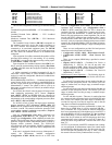
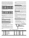
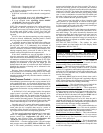
Table 73 — Staged Gas Heat Control Steps (Configuration
HEAT
SG.CT
HT.ST = 4)
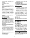
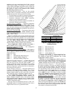
RELOCATE SAT (Supply Air Temperature) SENSOR FOR
HEATING IN LINKAGE APPLICATIONS — On CCN in-
stallations employing ComfortID™ terminals, the factory SAT
location must be changed to a new location downstream of the
unit’s heating system. The ComfortID terminal controls read
the SAT value for their “proof-of-heat” sequence before termi-
nals open to Minimum Heating positions during unit heating
sequence.
Determine a location in the supply duct that will provide a
fairly uniform airflow. Typically this would be a minimum of
5 equivalent duct diameters downstream of the unit. Also, care
should be taken to avoid placing the thermistor within a direct
line-of-sight of the heating element to avoid radiant effects.
Run a new two-wire conductor cable from the control box
through the low voltage conduit into the space inside the build-
ing and route the cable to the new sensor location.
Installing a New Sensor
— A field-provided duct-mount tem-
perature sensor (Carrier P/N 33ZCSENPAT or equivalent
10 kilo-ohm at 25 C NTC [negative temperature coefficient]
sensor) is required. Install the sensor through the side wall of
the duct and secure.
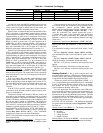
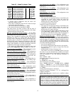
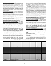
Table 74 — IGC LED Indicators
NOTES:
1. There is a 3-second pause between error code displays.
2. If more than one error code exists, all applicable error codes
will be displayed in numerical sequence.
3. Error codes on the IGC will be lost if power to the unit is
interrupted.
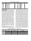
Re-Using the Factory SAT Sensor — The factory sensor is
attached to one of the supply fan housings. Disconnect the sen-
sor from the factory harness. Drill a hole insert the sensor
through the duct wall and secure in place.
Attach the new conductor cable to the sensor leads and ter-
minate in an appropriate junction box. Connect the opposite
end inside the unit control box at the factory leads from MBB
J8 terminals 11 and 12 (PNK) leads. Secure the unattached
PNK leads from the factory harness to ensure no accidental
contact with other terminals inside the control box.
MORNING WARM UP — Morning Warm Up is a period of
time that assists CCN linkage in opening up downstream zone
dampers for the first heating cycle of a day.
The Morning Warm Up Period is CCN linkage mode “2”
and is relayed in the following conditions:
• Temperature Compensated Start Mode is active AND Heat
Mode in effect AND LAT is warm enough or is to be
ignored due to placement.
• The unit just went into occupied mode and there has been
no cooling mode yet and a heat cycle occurs or was in prog-
ress when the unit went occupied.
In both cases, if and when the heat mode terminates, a heat
cycle has occurred and any subsequent heat cycles will not be
treated as a morning warm up period.
TEMPERING MODE — In a vent or cooling mode, the roof-
top may encounter a situation where the economizer at mini-
mum position is sending cold outside air down the ductwork of
the building. Therefore, it may be necessary to bring heat on to
counter-effect this low supply-air temperature. This is referred
to as the tempering mode.
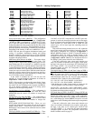
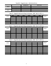
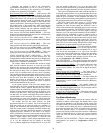
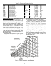
Setting up the System
— The relevant set points for Temper-
ing are located at the local display under Setpoints:
Operation
— First, the unit must be in a vent mode, a low cool
mode, or a high cool HVAC mode to be considered for a tem-
pering mode. Secondly, the tempering mode is only allowed
when the rooftop is configured for staged gas (Configuration
HEAT
HT.CF=3).
If the control is configured for staged gas, the control is in a
vent, low cool, or high cool HVAC mode, and the rooftop con-
trol is in a situation where the economizer must maintain a
minimum position, then the evaporator discharge temperature
(EDT) will be monitored. If the EDT falls below a particular
trip point then the tempering mode may be called out:
HVAC mode = “Tempering Vent”
STAGE
RELAY OUTPUT
CAPACITY
%
Heat 1 Heat 2 Heat 3 Heat 4 Heat 5 Heat 6
MBB-RLY8 MBB-RLY7 SCB-RLY1 SCB-RLY2 SCB-RLY3 SCB-RLY4
IGC1 MGV1 IGC2 MGV2 IGC3 MGV3
0 OFF OFF OFF OFF OFF OFF 0
1 ON OFF OFF OFF OFF OFF 19
2 ON ON OFF OFF OFF OFF 25
3 ON OFF OFF OFF ON OFF 38
4 ON ON OFF OFF ON OFF 44
5 ON ON OFF OFF ON ON 50
6 ON OFF ON OFF OFF OFF 57
7 ON ON ON OFF OFF OFF 63
8 ON OFF ON OFF ON OFF 76
9 ON OFF ON ON ON OFF 88
10 ON ON ON ON ON OFF 94
11 ON ON ON ON ON ON 100
LED INDICATION ERROR CODE
On Normal Operation
Off Hardware Failure
1 Flash Fan On/Off Delay Modified
2 Flashes Limit Switch Fault
3 Flashes Fame Sense Fault
4 Flashes Five Consecutive Limit Switch Faults
5 Flashes Ignition Lockout Fault
6 Flashes Ignition Switch Fault
7 Flashes Rollout Switch Fault
8 Flashes Internal Control Fault
9 Flashes Software Lockout
ITEM EXPANSION RANGE UNITS
CCN
POINT
DEFAULT
T.PRG
Tempering
Purge SASP
–20-80 dF TEMPPURG 50
T.CL
Tempering in
Cool SASP
5-75 dF TEMPCOOL 5
T.V.OC
Tempering Vent
Occ SASP
–20-80 dF TEMPVOCC 65
T.V.UN
Tempering Vent
Unocc. SASP
–20-80 dF TEMPVUNC 50