


69
IAQ Econo Override Pos (
Configuration
IAQ
AQ.SP
IQ.O.P) — This configuration is the position that the econo-
mizer goes to when override is in effect.
Diff. Air Quality Lo Limit (
Configuration
IAQ
AQ.SP
DAQ.L) — This is the differential CO
2
level at which IAQ
control of the dampers will be initiated.
Diff. Air Quality Hi Limit (
Configuration
IAQ
AQ.SP
DAQ.H) — This is the differential CO
2
level at which IAQ
control of the dampers will be at maximum and the dampers
will be at the Configuration
IAQ
DCV.C
EC.MN.
DAQ ppm Fan Off Set Point (
Configuration
IAQ
AQ.SP
D.F.OF) — This is the CO
2
level at which the
indoor fan will be turned off.
DAQ ppm Fan On Set Point (
Configuration
IAQ
AQ.SP
D.F.ON) — This is the CO
2
level at which
the indoor fan will be turned on.
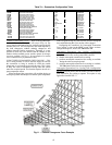
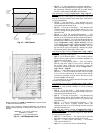
Diff. IAQ Responsiveness (
Configuration
IAQ
AQ.SP
IAQ.R) — This is the configuration that is used to select the
IAQ response curves as shown in Fig. 13.
OAQ Lockout Value (
Configuration
IAQ
AQ.SP
OAQ.L) — This is the maximum OAQ level above which de-
mand ventilation will be disabled.
User Determined OAQ (
Configuration
IAQ
AQ.SP
OAQ.U) — If an OAQ sensor is unavailable, the user can
manually set the OAQ reading.
IAQ Low Reference (
Configuration
IAQ
AQ.S.R
IQ.R.L) — This is the reference that will be used with a
non-Carrier IAQ sensor that may have a different characteristic
curve. It represents the CO
2
level at 4 mA.
IAQ High Reference (
Configuration
IAQ
AQ.S.R
IQ.R.H) — This is the reference that will be used with a
non-Carrier IAQ sensor that may have a different characteristic
curve. It represents the CO
2
level at 20 mA.
OAQ Low Reference (
Configuration
IAQ
AQ.S.R
OQ.R.L) — This is the reference that will be used with a
non-Carrier OAQ sensor that may have a different characteris-
tic curve. It represents the CO
2
level at 4 mA.
OAQ High Reference (
Configuration
IAQ
AQ.S.R
OQ.R.H) — This is the reference that will be used with a non-
Carrier OAQ sensor that may have a different characteristic
curve. It represents the CO
2
level at 20 mA.
PRE-OCCUPANCY PURGE — The control has the option
for a pre-occupancy purge to refresh the air in the space prior to
occupancy.
This feature is enabled by setting Configuration
IAQ
IAQ.P
IQ.PG to Yes.
The IAQ purge will operate under the following conditions:
• IQ.PG is enabled
• the unit is in the unoccupied state
• Current Time is valid
• Next Occupied Time is valid
• time is within two hours of the next occupied period
• time is within the purge duration (Configuration
IAQ
IAQ.P
IQ.P.T)
If all of the above conditions are met, the following logic is
used:
If OAT IQ.L.O and OAT OCSP and economizer is
available then purge will be enabled and the economizer will
be commanded to 100%.
If OAT < IQ.L.O then the economizer will be positioned to
the IAQ Purge LO Temp Min Pos (Configuration
IAQ
IAQ.P
IQ.P.L)
If neither of the above are true then the dampers will be
positioned to the IAQ Purge HI Temp Min Pos (Configuration
IAQ
IAQ.P
IQ.P.H)
If this mode is enabled the indoor fan and heat interlock
relay (VAV) will be energized.
IAQ Purge (
Configuration
IAQ
IAQ.P
IQ.PG) —
This is used to enable IAQ pre-occupancy purge.
IAQ Purge Duration (
Configuration
IAQ
IAQ.P
IQ.P.T) — This is the maximum amount of time that a purge
can occur.
IAQ Purge Lo Temp Min Pos (
Configuration
IAQ
IAQ.P
IQ.P.L) — This is used to configure a low limit for
damper position to be used during the purge mode.
IAQ Purge Hi Temp Min Pos (
Configuration
IAQ
IAQ.P
IQ.P.H) — This is used to configure a maximum po-
sition for the dampers to be used during the purge cycle.
IAQ Purge OAT Lockout Temp (
Configuration
IAQ
IAQ.P
IQ.L.O) — Nighttime lockout temperature below
which the purge cycle will be disabled.
Dehumidification and Reheat — The Dehumidifi-
cation function will override comfort condition set points
based on dry bulb temperature and deliver cooler air to the
space in order to satisfy a humidity set point at the space or
return air humidity sensor. The Reheat function will energize a
suitable heating system concurrent with dehumidification
sequence should the dehumidification operation result in
excessive cooling of the space condition.
The dehumidification sequence requires the installation of a
space or return air humidity sensor or a discrete switch input.
An ECB option is required to accommodate an RH (relative
humidity) sensor connection. A CEM (option or accessory) is
required to accomodate an RH switch. Reheat is possible when
multiple-step staged gas control option or hydronic heat field-
installed coil is installed. Reheat is also possible using a heat
reclaim coil (field-supplied and installed) or a DX (direct ex-
pansion) reheat coil.
Dehumidification and reheat control are allowed during
Cooling and Vent modes in the Occupied period.
On constant volume units using thermostat inputs (C.TYP =
3 or 4), the discrete switch input must be used as the dehumidi-
fication control input. The commercial Thermidistat™ device
is the recommended accessory device.
SETTING UP THE SYSTEM — The settings for dehumidi-
fication can be found at the local display at Configuration
DEHU. See Table 85.
Dehumidification Configuration (
D.SEL) — The dehumidi-
fication configuration can be set for the following settings:
• D.SEL = 0 — No dehumidification and reheat.
• D.SEL = 1 — The control will perform dehumidification
and reheat with staged gas only.
• D.SEL = 2 — The control will perform both dehumidifi-
cation and reheat with third party heat via an alarm relay.
In the case of D.SEL=2, during dehumidification, the
alarm relay will close to convey the need for reheat. A
typical application might be to energize a 3-way valve to
perform DX reheat.
Dehumidification Sensor (
D.SEN) — The sensor can be con-
figured for the following settings:
• D.SEN = 1 — Initiated by return air relative humidity
sensor.
• D.SEN = 2 — Initiated by discrete input.
Economizer Disable in Dehum Mode (
D.EC.D) — This
configuration determines economizer operation during Dehu-
midification mode.
• D.EC.D = YES — Economizer disabled during dehu-
midification (default).
• D.EC.D = NO — Economizer not disabled during dehu-
midification.