


65
CONSTANT VOLUME 2-STAGE CONTROL (BP.CF = 1)
OPERATION — Two exhaust fan relays will be turned on and
off based on economizer position. The two trip set points are
BP.P1 and BP.P2. If the economizer is greater than or equal
to BP.P1, then power exhaust stage 1 is requested and a
60-second timer is initialized. If the economizer is 5% below
the BP.P1, then power exhaust stage 1 is turned off. Also, if the
economizer position is less than BP.P1 and the 60-second timer
has expired, power exhaust stage 1 is turned off. The same
logic applies to the second power exhaust stage, except the
BP.P2 trip point is monitored. If the economizer position is
greater than or equal to BP.P2, then power exhaust stage 2
is energized and a 60-second timer is initialized. If the econo-
mizer is 5% below the BP.P2 the second power exhaust
stage turned off. If the economizer is less than BP.P2 and the
60-second timer has expired, second stage power exhaust is
turned off.
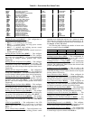
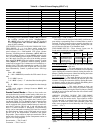
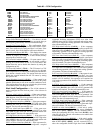
For BP.CF=1, the Table 82 illustrates the power exhaust
stages 1 and 2, relay combinations based upon Configuration
BP.MT (4 or 6 motors).
MULTIPLE POWER EXHAUST STAGE BUILDING
PRESSURE CONTROL (BP.CF = 2) OPERATION —
Building pressure control is active whenever the supply fan is
running. The control algorithm to be used (BP.SL=1) is a timed
threshold technique for bringing stages of power exhaust on
and off.
The number of power exhaust stages available for this con-
trol algorithm is a function of the number of motors it supports.
This number of motors is defined by the Configuration
BP
BP.MT configuration. Table 83 illustrates the staging tables
for this control algorithm based on BP.MT.
The following configurations are used in the controlling of
building pressure with this algorithm:
• Configuration
BP
B.CFG
BP.HP (building pressure
high threshold level)
• Configuration
BP
B.CFG
BP.LP (building pressure
low threshold level)
• Configuration
BP
B.CFG
BP.TM (building pressure
timer)
This control function is allowed to add or select power ex-
haust stages at any time, except that a delay time must expire
after a stage is added or subtracted. Any time a stage change is
made, a timer is started which delays staging for 10 * BP.TM
seconds. The default for BP.TM is 1, therefore the delay
between stage changes is set to 10 seconds.
The logic to add or subtract a stage of power exhaust is as
follows:
• If building pressure (Pressures
AIR.P
BP) is greater
than the building pressure set point (Configuration
BP
BPSP) plus the building pressure high threshold level
(Configuration
BP
B.CFG
BP.HP) add a stage of
power exhaust.
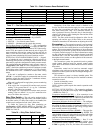
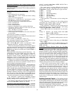
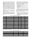
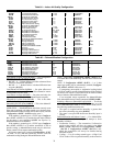
Table 81 — Building Pressure Configuration
*Some configurations are machine dependent.
Table 82 — Power Exhaust Staging (BP.CF = 1)
ITEM EXPANSION RANGE UNITS CCN POINT DEFAULT
BP BUILDING PRESS. CONFIG
BP.CF Building Press. Config 0-3 BLDG_CFG 0*
BP.RT Bldg.Pres.PID Run Rate 5-120 sec BPIDRATE 10
BP.P Bldg. Press. Prop. Gain 0-5 BLDGP_PG 0.5
BP.I Bldg.Press.Integ.Gain 0-2 BLDGP_IG 0.5
BP.D Bldg.Press.Deriv.Gain 0-5 BLDGP_DG 0.3
BP.SO BP Setpoint Offset 0.0 - 0.5 "H2O BPSO 0.05
BP.MN BP VFD Minimum Speed 0-100 % BLDGPMIN 10
BP.MX BP VFD Maximum Speed 0-100 % BLDGPMAX 100
BP.FS VFD/Act. Fire Speed/Pos. 0-100 % BLDGPFSO 100
BP.MT Power Exhaust Motors 1-2 PWRM 1*
BP.S Building Pressure Sensor Enable/Dsable BPSENS Dsable*
BP.R Bldg Press (+/–) Range 0 - 1.00 "H2O BP_RANGE 0.25
BP.SP Building Pressure Setp. -0.25 -> 0.25 "H2O BPSP 0.05
BP.P1 Power Exhaust On Setp.1 0 - 100 % PES1 35
BP.P2 Power Exhaust On Setp.2 0 - 100 % PES2 75
B.CFG BP ALGORITHM CONFIGS
BP.SL Modulating PE Alg. Slct. 1-3 BPSELECT 1
BP.TM BP PID Evaluation Time 0 - 10 min BPPERIOD 1
BP.ZG BP Threshold Adjustment 0.1 - 10.0 "H2O BPZ_GAIN 1
BP.HP High BP Level 0 - 1.000 "H2O BPHPLVL 0.05
BP.LP Low BP Level 0 - 1.000 "H2O BPLPLVL 0.04
BP.MT = 1 (4 motors) PE.A PE.B PE.C
Power Exhaust Stage 0 OFF OFF OFF
Power Exhaust Stage 1 OFF ON OFF
Power Exhaust Stage 2 ON ON ON
BP.MT = 2 (6 motors) PE.A PE.B PE.C
Power Exhaust Stage 0 OFF OFF OFF
Power Exhaust Stage 1 OFF OFF ON
Power Exhaust Stage 2 ON ON ON