


52
TEMPERATURE DRIVEN HEAT MODE EVALUATION —
This section discusses the control method for selecting a heat-
ing mode based on temperature. Regardless of whether the unit
is configured for return air or space temperature, the logic is ex-
actly the same. For the rest of this discussion, the temperature
in question will be referred to as the “controlling temperature.”
First, the occupied and unoccupied heating set points under
Setpoints must be configured.
Then, the heat/cool set point offsets under Configuration
D.LV.T should be set. See Table 66.
Related operating modes are under Operating Modes
MODE.
The first thing the control determines is whether the unit
is in the occupied mode (OCC) or in the temperature compen-
sated start mode (T.C.ST). If the unit is occupied or in tempera-
ture compensated start mode, the occupied heating set point
(OHSP) is used. In all other cases, the unoccupied heating
setpoint (UHSP) is used.
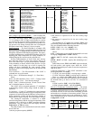
The control will call out a low or high heat mode by
comparing the controlling temperature to the heating set point
and the heating set point offset. The set point offsets are used as
additional help in customizing and tweaking comfort into the
building space.
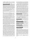
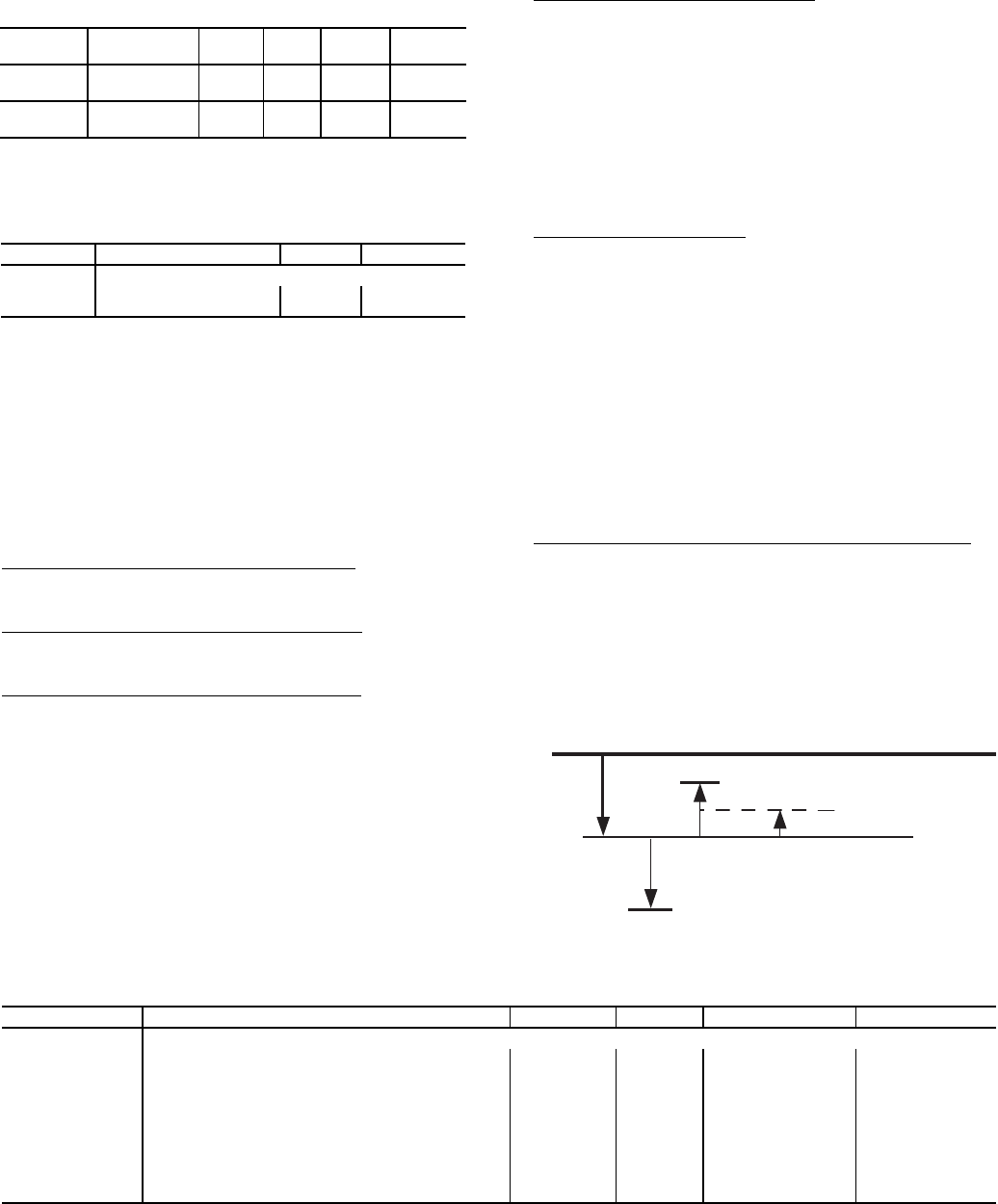
Demand Level Low Heat on Offset (
L.H.ON) — This is the
heating set point offset below the heating set point at which
point Low Heat starts.
Demand Level High Heat on Offset (
H.H.ON) — This is the
heating set point offset below the heating set point minus
L.H.ON at which point high heat starts.
Demand Level Low Heat Off Offset (
L.H.OF) — This is the
heating set point offset above the heating set point minus
L.H.ON at which point the Low Heat mode ends.
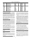
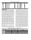
See Fig. 9 for an example of offsets.
To enter into a LOW HEAT mode, if the controlling temper-
ature falls below the heating set point minus L.H.ON, then
HVAC mode = LOW HEAT.
To enter into a HIGH HEAT mode, if the controlling tem-
perature falls below the heating set point minus L.H.ON minus
H.H.ON, then HVAC mode = HIGH HEAT.
To get out of a LOW HEAT mode, the controlling tempera-
ture must rise above the heating set point minus L.H.ON plus
L.H.OF.
To get out of a HIGH HEAT mode, the controlling tempera-
ture must rise above the heating set point minus L.H.ON plus
L.H.OF/2.
The Run Status table in the local display allows the user to
see the exact trip points for both the heating and cooling modes
without doing the calculations.
Heat Trend Demand Level (
H.T.LV) — This is the change in
demand that must be seen within the time period specified by
H.T.TM in order to hold off a HIGH HEAT mode regardless of
demand. This is not applicable to VAV control types (C.TYP=1
and 2) in the occupied period. This method of operation has
been referred to as “Comfort Trending.” As long as a LOW
HEAT mode is making progress in warming the space, the con-
trol will hold off on a HIGH HEAT mode. This is relevant for
the space sensor machine control types (C.TYP = 5 and 6) be-
cause they may transition into the occupied mode and see an
immediate and large heating demand when the set points
change.
Heat Trend Time (
H.T.TM) — This is the time period upon
which the heat trend demand level (H.T.LV) operates and may
work to hold off staging or a HIGH HEAT mode. This is not
applicable to VAV control types (C.TYP=1 and 2) in the
occupied period. See “Heat Trend Demand Level” section for
more details.
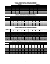
HEAT MODE DIAGNOSTIC HELP — To quickly deter-
mine the current trip points for the low and high heat modes,
there is a menu in the local display which lets the user quickly
view the state of the system. This menu also contains the cool
trip points as well. See Table 67 at the local display under Run
Status
TRIP.
The controlling temperature is “TEMP” and is in the middle
of the table for easy reference. Also, the “HVAC” mode can be
viewed at the bottom of the table.
HT.CF
= 1,2 (Two-Stage Gas and Electric Heat Control)
If the HVAC mode is LOW HEAT:
• If Electric Heat is configured, then the control will
request the supply fan ON
• If Gas Heat is configured, then the IGC indoor fan input
controls the supply fan request
• The control will turn on Heat Relay 1 (HS1)
• If Evaporator Discharge Temperature is less than 50 F,
then the control will turn on Heat Relay 2 (HS2)*
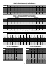
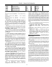
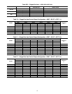
Table 66 — Heat/Cool Set Point Offsets
ITEM EXPANSION RANGE UNITS
CCN
POINT
DEFAULT
OHSP
Occupied Heat
Setpoint
55-80 dF OHSP 68
UHSP
Unoccupied
Heat Setpoint
40-80 dF UHSP 55
ITEM EXPANSION RANGE CCN POINT
MODE MODES CONTROLLING UNIT
OCC Currently Occupied ON/OFF MODEOCCP
T.C.ST Temp.Compensated Start ON/OFF MODETCST
ITEM EXPANSION RANGE UNITS CCN POINT DEFAULT
D.LV.T COOL/HEAT SETPT. OFFSETS
L.H.ON Dmd Level Lo Heat On -1 - 2 ^F DMDLHON 1.5
H.H.ON Dmd Level(+) Hi Heat On 0.5 - 20.0 ^F DMDHHON 0.5
L.H.OF Dmd Level(-) Lo Heat Off 0.5 - 2 ^F DMDLHOFF 1
L.C.ON Dmd Level Lo Cool On -1 - 2 ^F DMDLCON 1.5
H.C.ON Dmd Level(+) Hi Cool On 0.5 - 20.0 ^F DMDHCON 0.5
L.C.OF Dmd Level(-) Lo Cool Off 0.5 - 2 ^F DMDLCOFF 1
C.T.LV Cool Trend Demand Level 0.1 - 5 ^F CTRENDLV 0.1
H.T.LV Heat Trend Demand Level 0.1 - 5 ^F HTRENDLV 0.1
C.T.TM Cool Trend Time 30 - 600 sec CTRENDTM 120
H.T.TM Heat Trend Time 30 - 600 sec HTRENDTM 120
H.H.ON
L.H.OF
L.H.OF/2
L.H.ON
the "Heating Setpoint"
Fig. 9 — Heating Offsets
A48-7702