


50
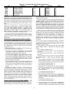
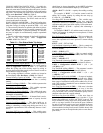
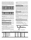
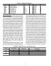
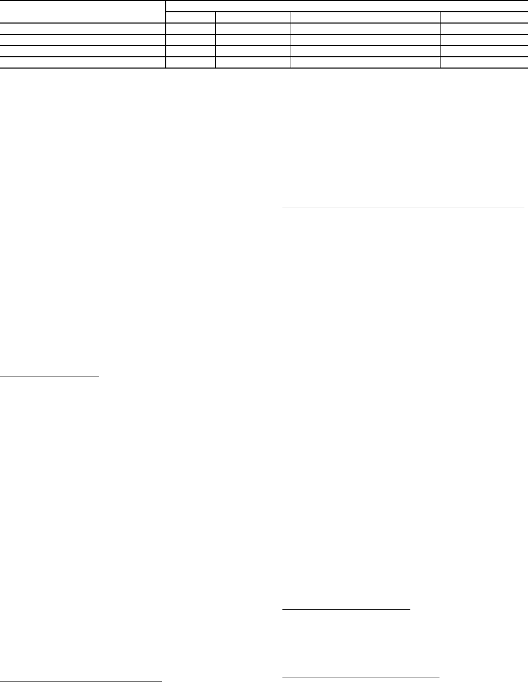
Table 64 — Condenser Fan Staging
* For size 60 ton units with MCHX condensers, MBB – Relay 6 drives OFC4 and compressor contactor B1 or B2 auxiliary contacts drive OFC1.
For 060 size units with MCHX condensers, there are four
outdoor fans, two for each independent refrigerant circuit. The
control cycles two stages of outdoor fans for each circuit, one
fan per stage, to maintain acceptable head pressure.
When a circuit A compressor has been commanded on, then
OFC3 is energized via the normally opened auxiliary contacts
on the compressor contactors. The auxiliary contacts are wired
such that turning on either circuit A compressor will energize
OFC3. Contactor OFC3 will remain on until all circuit A com-
pressors have been commanded off. If SCTA is above the
HPSP or if OAT is greater than 75 F, then condenser fan A
(MBB Relay 6) will be energized (CD.F.A = ON) turning on
OFC4. Condenser fan A will remain on until all compressors
have been commanded off, or SCTA drops 40 F below the
HPSP for greater than 2 minutes and OAT is less than 73 F.
When a circuit B compressor has been commanded on, then
OFC1 is energized via the normally opened auxiliary contacts
on the compressor contactors. The auxiliary contacts are wired
such that turning on either circuit B compressor will energize
OFC1. Contactor OFC1 will remain on until all circuit B com-
pressors have been commanded off. If SCTB is above the
HPSP or if OAT is greater than 75 F, then condenser fan B
(MBB Relay 5) will be energized (CD.F.B = ON) turning on
OFC2. Condenser fan B will remain on until all compressors
have been commanded off, or SCTB drops 40 F below the
HPSP for greater than 2 minutes and OAT is less than 73 F.
Failure Mode Operation
— If either of the SCT or DPT sen-
sors fails, then the control defaults to head pressure control
based on the OAT sensor. The control turns on the second fan
stage when the OAT is above 65 F and stages down when OAT
drops below 50 F.
If the OAT sensor fails, then the control defaults to head
pressure control based on the SCT sensors. The control turns
on the second fan stage when the highest active circuit SCT is
above the HPSP and stages down when the highest active cir-
cuit SCT drops 40 F below the HPSP for longer than
2 minutes.
If the SCT, DPT, and OAT sensors have all failed, then the
control turns on the first and second fan stages when any com-
pressor is commanded on.
Compressor current sensor boards (CSB) are used on all
units and are able to diagnose a compressor stuck on (welded
contactor) condition. If the control commands a compressor off
and the CSB detects current flowing to the compressor, then
the first fan stage is turned on immediately. The second fan
stage will turn on when OAT rises above 75 F or the highest ac-
tive circuit SCT rises above the HPSP and remain on until the
condition is repaired regardless of the OAT and SCT values.
ECONOMIZER INTEGRATION WITH MECHANICAL
COOLING — When the economizer is able to provide free
cooling (Run Status
ECON
ACTV = YES), mechanical
cooling may be delayed or even held off indefinitely.
NOTE: Once mechanical cooling has started, this delay logic
is no longer relevant.
Economizer Mechanical Cooling Delay
— This type of me-
chanical cooling delay is relevant to the all machine control
types.
If the economizer is able to provide free cooling at the start
of a cooling session, the mechanical cooling algorithm checks
the economizer’s current position (Run Status
ECON
ECN.P) and compares it to the economizer’s maxi-
mum position (Configuration
ECON
EC.MX) – 5%.
Once the economizer has opened beyond this point a
2.5-minute timer starts. If the economizer stays beyond this
point for 2.5 minutes continuously, the mechanical cooling
algorithm is allowed to start computing demand and stage
compressors.
Economizer Control Point (
Run Status
VIEW
EC.C.P)
— There are 4 different ways to determine the economizer
control point when the economizer is able to provide free
cooling:
If no mechanical cooling is active and HVAC mode = LOW
COOL
EC.C.P = Setpoints
SA.LO + Inputs
RSET
SA.S.R
If no mechanical cooling is active and HVAC mode = HIGH
COOL
EC.C.P = Setpoints
SA.HI + Inputs
RSET
SA.S.R
When the first stage of mechanical cooling has started
EC.C.P = 53 F plus any economizer suction pressure reset
applied
When the second stage of mechanical cooling has started
EC.C.P = 48 F plus any economizer suction pressure reset
applied
Heating Control — The A Series ComfortLink™ con-
trol system offers control for 3 different types of heating systems
to satisfy general space heating requirements: 2-stage gas heat,
2-stage electric heat and multiple-stage (staged) gas heat.
Variable air volume (VAV) type applications (C.TYP = 1, 2,
3, or 5) require that the space terminal positions be commanded
to open to Minimum Heating positions when gas or electric
heat systems are active, to provide for the unit heating
system’s Minimum Heating Airflow rate.
For VAV applications, the heat interlock relay (HIR) func-
tion provides the switching of a control signal intended for use
by the VAV terminals. This signal must be used to command
the terminals to open to their Heating Open positions. The HIR
is energized whenever the Heating mode is active, an IAQ pre-
occupied force is active, or if fire smoke modes, pressurization,
or smoke purge modes are active.
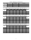
SETTING UP THE SYSTEM — The heating configurations
are located at the local display under Configuration
HEAT.
See Table 65.
Heating Control Type (
HT.CF) — The heating control types
available are selected with this variable.
0 = No Heat
1 = Electric Heat
2 = 2 Stage Gas Heat
3 = Staged Gas Heat
Heating Supply Air Set Point (
HT.SP) — In a low heat mode
for staged gas heat, this is the supply air set point for heating.
FAN RELAY
48/50A UNIT SIZE
020-035 036-050 051,060 060 with MCHX
OFC1,4* (MBB - RELAY 6) OFM1 OFM1, OFM2 OFM1, OFM2 OFM4
OFC2 (MBB - RELAY 5) OFM2 OFM3, OFM4 OFM3, OFM4, OFM5, OFM6 OFM2
OFC3 C.A1-AUX or C.A2-AUX NA NA NA OFM3
OFC1* C.B1-AUX or C.B2-AUX NA NA NA OFM1