


48
MAT Calc Config (MAT.S) — This configuration gives the
user two options in the processing of the mixed-air temperature
(MAT) calculation:
• MAT.S = 0
There will be no MAT calculation.
• MAT.S = 1
The control will attempt to learn MAT over time. Any time
the system is in a vent mode and the economizer stays at a
particular position for long enough, MAT = EDT. Using this
method, the control has an internal table whereby it can
more closely determine the true MAT value.
• MAT.S = 2
The control will not attempt to learn MAT over time.
To calculate MAT linearly, the user should reset the MAT
table entries by setting MAT.R to YES. Then set MAT.S = 2.
The control will calculate MAT based on the position of the
economizer and outside air and return air temperature.
To freeze the MAT table entries, let the unit run with MAT.S
= 1. Once sufficient data has been collected, change MAT.S
= 2. Do not reset the MAT table.
Reset MAT Table Entries? (MAT.R) — This configuration
allows the user to reset the internally stored MAT learned
configuration data back to the default values. The defaults are
set to a linear relationship between the economizer damper
position and OAT and RAT in the calculation of MAT.
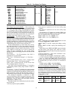
SumZ Overrides
— There are a number of overrides to the
SumZ algorithm which may add or subtract stages of cooling.
• High Temp Cap Override (H.TMP)
• Low Temp Cap Override (L.TMP)
• Pull Down Cap Override (PULL)
• Slow Change Cap Override (SLOW)
Economizer Trim Override
— The unit may drop stages of
cooling when the economizer is performing free cooling and
the configuration Configuration
ECON
E.TRM is set to
Yes. The economizer controls to the same supply air set point
as mechanical cooling does for SumZ when E.TRM = Yes.
This allows for much tighter temperature control as well as cut-
ting down on the cycling of compressors.
For a long cooling session where the outside-air tempera-
ture may drop over time, there may be a point at which the
economizer has closed down far enough were the unit could
remove a cooling stage and open up the economizer further to
make up the difference.
Mechanical Cooling Lockout (
Configuration
COOL
MC.LO) — This configuration allows a configurable outside-
air temperature set point below which mechanical cooling will
be completely locked out.
DEMAND LIMIT CONTROL — Demand Limit Control
may override the cooling algorithm to limit or reduce cooling
capacity during run time. The term Demand Limit Control re-
fers to the restriction of machine capacity to control the amount
of power that a machine will use. This can save the owner
money by limiting peaks in the power supply. Demand limit
control is intended to interface with an external Loadshed De-
vice either through CCN communications, external switches,
or 4 to 20 mA input.
The control has the capability of loadshedding and limiting
in 3 ways:
• Two discrete inputs tied to configurable demand limit set
point percentages.
• An external 4 to 20 mA input that can reset capacity back
linearly to a set point percentage.
• CCN loadshed functionality.
NOTE: It is also possible to force the demand limit variable
(Run Status
COOL
DEM.L).
To use Demand Limiting, select the type of demand limiting
to use. This is done with the Demand Limit Select configura-
tion (Configuration
DMD.L
DM.L.S).
To view the current demand limiting currently in effect,
look at Run Status
COOL
DEM.L.
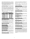
The configurations associated with demand limiting can be
viewed at the local display at Configuration
DMD.L. See
Table 63.
Demand Limit Select (
DM.L.S) — This configuration deter-
mines the type of demand limiting.
• 0 = NONE — Demand Limiting not configured.
• 1 = 2 SWITCHES — This will enable switch input
demand limiting using the switch inputs connected to the
CEM board. Connections should be made to TB6-4,5,6.
• 2 = 4 to 20 mA — This will enable the use of a remote 4
to 20 mA demand limit signal. The CEM module must
be used. The 4 to 20 mA signal must come from an
externally sourced controller and should be connected to
TB6-7,8.
• 3 = CCN LOADSHED — This will allow for loadshed
and red lining through CCN communications.
Two-Switch Demand Limiting (DM.L.S = 1) — This type of
demand limiting utilizes two discrete inputs:
Demand Limit Switch 1 Setpoint (D.L.S1) — Dmd Limit
Switch Setpoint 1 (0-100% total capacity)
Demand Limit 2 Setpoint (D.L.S2) — Dmd Limit Switch
Setpoint 2 (0-100% total capacity)
The state of the discrete switch inputs can be found at the lo-
cal display:
Inputs
GEN.I
DL.S1
Inputs
GEN.I
DL.S2
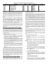
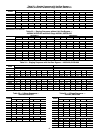
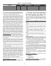
The following table illustrates the demand limiting (Run
Status
COOL
DEM.L) that will be in effect based on the
logic of the applied switches:
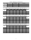
4-20 mA Demand Limiting (DM.L.S = 2) — If the unit has
been configured for 4 to 20 mA demand limiting, then the
Inputs
4-20
DML.M value is used to determine the
amount of demand limiting in effect (Run Sta-
tus
COOL
DEM.L). The Demand Limit at 20 mA
(D.L.20) configuration must be set. This is the configured
demand limit corresponding to a 20 mA input (0 to 100%).
The value of percentage reset is determined by a linear
interpolation from 0% to “D.L.20”% based on the Inputs
4-20
DML.M input value.
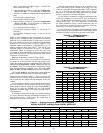
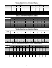
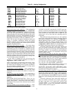
The following examples illustrate the demand limiting
(Run Status
COOL
DEM.L) that will be in effect based on
amount of current seen at the 4 to 20 mA input, DML.M.
CCN Loadshed Demand Limiting (DM.L.S = 3) — If the unit
has been configured for CCN Loadshed Demand Limiting,
then the demand limiting variable (Run Status
COOL
DEM.L) is controlled via CCN commands.
Switch Status Run Status
COOL
DEM.L = 1
Inputs
GEN.I
DL.S1 = OFF
Inputs
GEN.I
DL.S2 = OFF
100%
Inputs
GEN.I
DL.S1= ON
Inputs
GEN.I
DL.S2 = OFF
Configuration
DMD.L
D.L.S1
Inputs
GEN.I
DL.S1= ON
Inputs
GEN.I
DL.S2 = ON
Configuration
DMD.L
D.L.S2
Inputs
GEN.I
DL.S1= OFF
Inputs
GEN.I
DL.S2 = ON
Configuration
DMD.L
D.L.S2
D.L.20 = 80% D.L.20 = 80% D.L.20 = 80%
DML.M = 4mA DML.M = 12 mA DML.M = 20mA
DEM.L = 100% DEM.L = 90% DEM.L = 80%