


161
APPENDIX C — VFD INFORMATION
On variable air volume units with optional VFD, the supply
fan speed is controlled by a 3-phase VFD. The VFD is located
in the supply fan section behind a removable panel. The VFD
speed is controlled directly by the ComfortLink™ controls
through a 4 to 20 mA signal based on a supply duct pressure
sensor. The VFD has a display, which can be used for service
diagnostics, but setup of the building pressure and control loop
factors should be done through the scrolling marquee display.
The VFD is powered during normal operation to prevent
condensation from forming on the boards during the off mode
and is stopped by driving the speed to 0 (by sending a 4 mA
signal to the VFD).
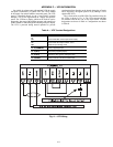
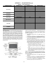
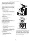
The A Series units use ABB VFDs. The interface wiring for
the VFDs is shown in Fig. A. The VFD connects through
an isolation board to the 4 to 20 mA RCB board. Terminal
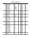
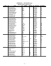
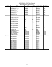
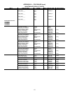
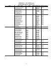
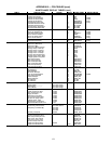
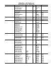
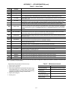
designations are shown in Table A. Configurations are shown
in Table B.
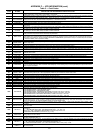
Table A — VFD Terminal Designations
TERMINAL FUNCTION
U1
V1
W1 Three-Phase Main Circuit Input Power Supply
U2
V2 Three-Phase AC Output to Motor, 0 V to
W2 Maximum Input Voltage Level
X1-11 (GND)
X1-12 (COMMON) Factory-supplied jumper
X1-10 (24 VDC)
X1-13 (DI-1) Run (factory-supplied jumper)
X1-10 (24 VDC) Start Enable 1 (Factory-supplied jumper). When
X1-16 (DI-4) opened the drive goes to emergency stop.
X1-2 (AI-1)
X1-3 (AGND) Factory wired for 4 to 20 mA remote input
Fig. A — VFD Wiring
A48-7712