


60
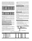
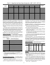
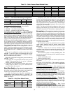
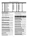
Table 76 — Static Pressure Reset Related Points
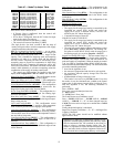
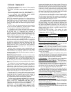
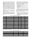
Table 77 — Fan Status Monitoring Configuration
Fan Stat Monitoring Type (
SFS.M) — This configuration se-
lects the type of fan status monitoring to be performed.
0 - NONE — No switch or monitoring
1 - SWITCH — Use of the fan status switch
2 - SP RISE — Monitoring of the supply duct pressure.
Fan Fail Shuts Down Unit (
SFS.S) — This configuration
will configure the unit to shut down on a supply fan status fail
or simply alert the condition and continue to run. When config-
ured to YES, the control will shut down the unit if supply fan
status monitoring fails and the control will also send out an
alarm. If set to NO, the control will not shut down the unit if
supply fan status monitoring fails but will send out an alert.
SUPPLY FAN STATUS MONITORING LOGIC — Regard-
less of whether the user is monitoring a discrete switch or is
monitoring static pressure, the timing for both methods are the
same and rely upon the configuration of static pressure control.
The configuration that determines static pressure control is
Configuration
SP
SP.CF. If this configuration is set to 0
(none), a fan failure condition must wait 60 continuous seconds
before taking action. If this configuration is 1 (VFD), a fan fail-
ure condition must wait 3 continuous minutes before taking
action.
If the unit is configured to monitor a fan status switch
(SFS.M = 1), and if the supply fan commanded state does not
match the supply fan status switch for 3 continuous minutes,
then a fan status failure has occurred.
If the unit is configured for supply duct pressure monitoring
(SFS.M = 2), then
• If the supply fan is requested ON and the static pressure
reading is not greater than 0.2 in. wg for 3 continuous
minutes, a fan failure has occurred.
• If the supply fan is requested OFF and the static pressure
reading is not less than 0.2 in. wg for 3 continuous min-
utes, a fan failure has occurred.
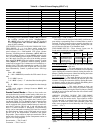
Dirty Filter Switch — The unit can be equipped with a
field-installed accessory dirty filter switch. The switch is located
in the filter section. If a dirty filter switch is not installed, the
switch input is configured to read “clean” all the time.
To enable the sensor for dirty filter monitoring set
Configuration
UNIT
SENS
FLT.S to ENABLE. The
state of the filter status switch can be read at Inputs
GEN.I
FLT.S. See Table 78.
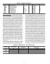
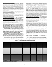
Table 78 — Dirty Filter Switch Points
Monitoring of the filter status switch is disabled in the
Service Test mode and when the supply fan is not commanded
on. If the fan is on and the unit is not in a test mode and the
filter status switch reads “dirty” for 2 continuous minutes, an
alert is generated. Recovery from this alert is done through a
clearing of all alarms or after cleaning the filter and the switch
reads “clean” for 30 seconds.
NOTE: The filter switch should be adjusted to allow for the
operating cfm and the type of filter. Refer to the accessory
installation instructions for information on adjusting the switch.
Economizer — The economizer control is used to manage
the outside and return air dampers of the unit to provide venti-
lation air as well as free cooling based on several configuration
options. This section contains a description of the economizer
and its ability to provide free cooling. See the section on Indoor
Air Quality Control on page 67 for more information on setting
up and using the economizer to perform demand controlled
ventilation (DCV). See the Third Party Control section for a
description on how to take over the operation of the economiz-
er through external control.
The economizer system also permits this unit to perform
smoke control functions based on external control switch
inputs. Refer to the Smoke Control Modes section for detailed
discussions.
Economizer control can be based on automatic control
algorithms using unit-based set points and sensor inputs. This
economizer control system can also be managed through exter-
nal logic systems.
The economizer system is a factory-installed option. This
unit can also have the following devices installed to enhance
economizer control:
• Outside air humidity sensor
• Return air humidity sensor
NOTE: All these options require the controls expansion mod-
ule (CEM).
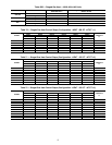
SETTING UP THE SYSTEM — The economizer configura-
tion options are under the Local Display Mode Configuration
ECON. See Table 79.
Economizer Installed? (
EC.EN) — If an economizer is not
installed or is to be completely disabled then the configuration
option EC.EN should be set to No. Otherwise in the case of an
installed economizer, this value must be set to Yes.
Economizer Minimum Position (
EC.MN) — The configura-
tion option EC.MN is the economizer minimum position. See
the section on indoor air quality for further information on how
to reset the economizer further to gain energy savings and to
more carefully monitor IAQ problems.
Economizer Maximum Position (
EC.MX) — The upper lim-
it of the economizer may be limited by setting EC.MX. This
value defaults to 98% to avoid problems associated with slight
changes in the economizer damper’s end stop over time. Typi-
cally this will not need to be adjusted.
Economizer Trim for Sum Z? (
E.TRM) — Sum Z is the
adaptive cooling control algorithm used for multiple stages
of mechanical cooling capacity. The configuration option,
E.TRM is typically set to Yes, and allows the economizer to
ITEM EXPANSION RANGE UNITS CCN POINT DEFAULT
Inputs
4-20 SP.M Static Pressure mA 4-20 mA SP_MA
4-20 SP.M.T Static Pressure mA Trim -2.0 - +2.0 mA SPMATRIM
4-20 SP.R.M Static Pressure Reset mA 4-20 mA SPRST_MA 0.0
RSET SP.RS Static Pressure Reset 0.0-3.0 in. wg SPRESET 0.0
Outputs
Fans S.VFD Supply Fan VFD Speed 0-100 % SFAN_VFD
ITEM EXPANSION RANGE CCN POINT
SFS.S Fan Fail Shuts Down Unit Yes/No SFS_SHUT
SFS.M Fan Stat Monitoring Type 0 - 2 SFS_MON
ITEM EXPANSION RANGE
CCN
POINT
ConfigurationUNIT
SENSFLT.S
Filter
Stat.Sw.Enabled ?
Enable/
Disable
FLTS_ENA
InputsGEN.I
FLT.S
Filter Status Input DRTY/CLN FLTS