


63
Unoccupied Economizer Free Cooling Outside Lockout
Temperature (FC.LO) — This configuration option allows
the user to select an outside-air temperature below which unoc-
cupied free cooling is not allowed. This is further explained in
the logic section.
Unoccupied Economizer Free Cooling Logic
— The follow-
ing qualifications that must be true for unoccupied free cooling
to operate:
• Unit configured for an economizer
• Space temperature sensor enabled and sensor reading
within limits
• Unit is in the unoccupied mode
• FC.CF set to 1 or FC.CF set to 2 and control is within
FC.TM minutes of the next occupied period
• Not in the Temperature Compensated Start Mode
• Not in a cooling mode
• Not in a heating mode
• Not in a tempering mode
• Outside-air temperature sensor reading within limits
• Economizer would be allowed to cool if the fan were
requested and in a cool mode
•OAT > FC.LO (1.0° F hysteresis applied)
• Unit not in a fire smoke mode
• No fan failure when configured to for unit to shut down
on a fan failure
If all of the above conditions are satisfied:
Unoccupied Economizer Free Cooling will start when both of
the following conditions are true:
{SPT > (OCSP + 2)} AND {SPT > (OAT + 8)}
The Unoccupied Economizer Free Cooling Mode will stop
when either of the following conditions are true:
{SPT < OCSP} OR {SPT < (OAT + 3)} where SPT = Space
Temperature and OCSP = Occupied Cooling Set Point.
When the Unoccupied Economizer Free Cooling mode is
active, the supply fan is turned on and the economizer damper
modulated to control to the supply air set point (Setpoints
SASP) plus any supply air reset that may be applied (Inputs
RSET
SA.S.R).
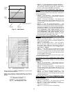
ECONOMIZER OPERATION CONFIGURATION — The
configuration items in the E.CFG menu group affect how
the economizer modulates when attempting to follow an
economizer cooling set point. Typically, they will not need
adjustment. In fact, it is strongly advised not to adjust these
configuration items from their default settings without first
consulting a service engineering representative.
In addition, the economizer cooling algorithm is designed to
automatically slow down the economizer actuator’s rate of
travel as outside air temperature decreases.
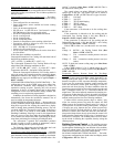
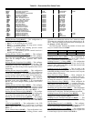
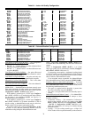
ECONOMIZER DIAGNOSTIC HELP — Because there are
so many conditions which might disable the economizer from
being able to provide free cooling, the control has a display
table to identify these potentially disabling sources. The user
can check ACTV, the “Economizer Active” flag. If this flag is
set to Yes there is no reason to check DISA (Economizer
Disabling Conditions). If the flag is set to No, this means that at
least one or more of the flags under the group DISA are set
to Yes and the user can discover what is preventing the econo-
mizer from performing free cooling by checking the table.
The economizer’s reported and commanded positions
are also viewable, as well as outside air temperature, relative
humidity, enthalpy and dew point temperature.
The following information can be found under the Local
Display Mode Run Status
ECON. See Table 80.
Economizer Control Point Determination Logic
— Once the
economizer is allowed to provide free cooling, the economizer
must determine exactly what set point it should try to maintain.
The set point the economizer attempts to maintain when “free
cooling” is located at Run Status
VIEW
EC.C.P. This is
the economizer control point.
The control selects set points differently, based on the
control type of the unit. This control type can be found at
Configuration
UNIT
C.TYP. There are 6 types of control.
C.TYP = 1 VAV-RAT
C.TYP = 2 VAV-SPT
C.TYP = 3 TSTAT Multi-Staging
C.TYP = 4 TSTAT 2 Stage
C.TYP = 5 SPT Multi-Staging
C.TYP = 6 SPT 2 Stage
If the economizer is not allowed to do free cooling, then
EC.C.P = 0.
If the economizer is allowed to do free cooling and the
Unoccupied Free Cooling Mode is ON, then EC.C.P =
Setpoints
SASP + Inputs
RSET
SA.S.R.
If the economizer is allowed to do free cooling and the
Dehumidification mode is ON, then EC.C.P = the Cooling
Control Point (Run Status
VIEW
CL.C.P).
If the C.TYP is either 4 or 6, and the unit is in a cool mode,
then
If Stage = 0 EC.C.P = the Cooling Control Point (Run
Status
VIEW
CL.C.P)
If Stage = 1 53.0 + economizer suction pressure reset (see
below)
If Stage = 2 48.0 + economizer suction pressure reset (see
below)
NOTE: To check the current cooling stage go to Run Status
Cool
CUR.S.
If the C.TYP is either 1,2,3 or 5, and the unit is in a cool
mode, then EC.C.P = the Cooling Control Point (Run Status
VIEW
CL.C.P).
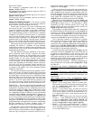
Economizer Suction Pressure Reset for Two-Stage
Cooling — If the unit’s control type is set to either 2-stage ther-
mostat or 2-stage space temperature control, then there is no
cooling control point. Stages 1 and 2 are brought on based on
demand, irrespective of the evaporator discharge temperature.
In this case, the economizer monitors suction pressure and
resets the economizer control point accordingly in order to
protect the unit from freezing. For those conditions when the
economizer opens up fully but is not able to make set point, and
then a compressor comes on, it is conceivable that the coil
might freeze. This can be indirectly monitored by checking suc-
tion pressure. Rather than fail a circuit, the control will attempt
to protect the unit by resetting the economizer control point
until the suction pressure rises out of freezing conditions.
If either circuit’s suction pressure drops to within 5 psig
of the low suction pressure trip point, the control will start
adding reset to the economizer control point if it is active. It
will be possible to reset the control point upwards, 10 degrees
(2 degrees per psig), between the low suction pressure trip
point of 52 psig for 48/50AJ,AK,AW,AY units or 93 psig for
48/50A2,A3,A4,A5 units. If this does not work, and if the suc-
tion pressure drops below the trip point, then the control will
further reset the control point 1 degree every 15 seconds up to a
maximum of 10 degrees. The resulting effect will be to warm
up the mixed air entering the evaporator, thereby raising the
suction pressure.
Building Pressure Control — The building pressure
control sequence provides control of the pressure in the build-
ing through the modulating flow rate function of the modulat-
ing power exhaust option. This function also provides control
of the constant volume 2-stage power exhaust option.
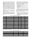
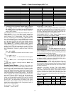
BUILDING PRESSURE CONFIGURATION — The build-
ing pressure configurations are found at the local display under
Configuration
BP. See Table 81.