


66
Table 83 — Power Exhaust Staging (BP.CF = 2)
• If building pressure (Pressures
AIR.P
BP) is less than
the building pressure set point (Configuration
BP
BPSP) minus the building pressure low threshold
level (Configuration
BP
B.CFG
BP.LP) subtract a
stage of power exhaust.
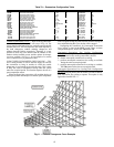
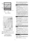
VFD POWER EXHAUST BUILDING PRESSURE CON-
TROL (BP.CF = 3) — A 4 to 20mA analog output from
Economizer Control Board 1 (ECB-1, AO1) is provided as a
speed reference for a field-installed VFD power exhaust
accessory. If building pressure (Pressures
AIR.P
BP) rises
above the building pressure set point (BP.SP) and the supply
fan is on, then building pressure control is initialized. Thereaf-
ter, if the supply fan relay goes off or if the building pressure
drops below the BP.SP minus the building pressure set point
offset (BP.SO) for 5 continuous minutes, building pressure
control will be stopped. The 5-minute timer will continue to re-
initialize if the VFD is still commanded to a speed > 0%. If the
building pressure falls below the set point, the VFD will slow
down automatically. Control is performed with a PID loop
where:
Error = BP – BP.SP
K = 1000 * BP.RT/60 (normalize the PID control for run
rate)
P = K * BP.P * (error)
I = K * BP.I * (error) + “I” calculated last time through the
PID
D = K * BP.D * (error – error computed last time through
the PID)
VFD speed reference (clamped between BP.MN and
BP.MX%) = P + I + D
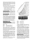
Smoke Control Modes — There are four smoke con-
trol modes that can be used to control smoke within areas ser-
viced by the unit: Pressurization mode, Evacuation mode,
Smoke Purge mode, and Fire Shutdown. Evacuation, Pressur-
ization and Smoke Purge modes require the Controls Expan-
sion Board (CEM). The Fire Shutdown input is located on the
main board (MBB) on terminals TB5-10 and 11. The unit may
also be equipped with a factory-installed return air smoke de-
tector that is wired to TB5-10 and 11 and will shut the unit
down if a smoke condition is determined. Field-monitoring
wiring can be connected to terminal TB5-8 and 9 to monitor
the smoke detector. Inputs on the CEM board can be used to
put the unit in the Pressurization, Evacuation, and Smoke
Purge modes. These switches or inputs are connected to TB6 as
shown below. Refer to Major System Components section on
page 101 for wiring diagrams.
Pressurization — TB6-12 and 13
Evacuation — TB6-13 and 14
Smoke Purge — TB6-13 and 15
Each mode must be energized individually on discrete in-
puts and the corresponding alarm is initiated when a mode is
activated. The fire system provides a normally closed dry con-
tact closure. Multiple smoke control inputs, sensed by the con-
trol will force the unit into a Fire Shutdown mode.
FIRE-SMOKE INPUTS — These discrete inputs can be
found on the local display under Inputs
FIRE.
Fire Shutdown Mode
— This mode will cause an immediate
and complete shutdown of the unit.
Pressurization Mode
— This mode attempts to raise the pres-
sure of a space to prevent smoke infiltration from an adjacent
space. Opening the economizer (thereby closing the return air
damper), shutting down power exhaust and turning the indoor
fan on will increase pressure in the space.
Evacuation Mode
— This mode attempts to lower the pres-
sure of the space to prevent infiltrating an adjacent space with
its smoke. Closing the economizer (thereby opening the return-
air damper), turning on the power exhaust and shutting down
the indoor fan decrease pressure in the space.
Smoke Purge Mode
— This mode attempts to draw out
smoke from the space after the emergency condition. Opening
the economizer (thereby closing the return-air damper), turning
on both the power exhaust and indoor fan will evacuate smoke
and bring in fresh air.
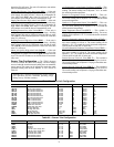
AIRFLOW CONTROL DURING THE FIRE-SMOKE
MODES — All non-smoke related control outputs will get
shut down in the fire-smoke modes. Those related to airflow
will be controlled as explained below. The following matrix
specifies all actions the control shall undertake when each
mode occurs (outputs are forced internally with CCN priority
number 1 - “Fire”):
*“FSO” refers to the supply VFD fire speed override configurable
speed.
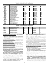
BP.MT = 1 (4 motors) PE.A PE.B PE.C
Power Exhaust Stage 0 OFF OFF OFF
Power Exhaust Stage 1 ON OFF OFF
Power Exhaust Stage 2 OFF ON OFF
Power Exhaust Stage 3 ON ON OFF
Power Exhaust Stage 4 ON ON ON
BP.MT = 2 (6 motors) PE.A PE.B PE.C
Power Exhaust Stage 0 OFF OFF OFF
Power Exhaust Stage 1 ON OFF OFF
Power Exhaust Stage 2 OFF ON OFF
Power Exhaust Stage 3 ON ON OFF
Power Exhaust Stage 4 ON OFF ON
Power Exhaust Stage 5 OFF ON ON
Power Exhaust Stage 6 ON ON ON
ITEM EXPANSION RANGE
CCN
POINT
WRITE
STATUS
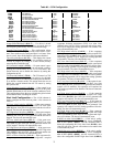
FIRE FIRE-SMOKE INPUTS
FSD Fire Shutdown Input ALRM/NORM FSD forcible
PRES Pressurization Input ALRM/NORM PRES forcible
EVAC Evacuation Input ALRM/NORM EVAC forcible
PURG Smoke Purge Input ALRM/NORM PURG forcible
DEVICE PRESSURIZATION PURGE EVACUATION
FIRE
SHUTDOWN
Economizer 100% 100% 0% 0%
Indoor Fan —
VFD
ON/FSO* ON/FSO* OFF OFF
Power Exhaust OFF ON/FSO* ON/FSO* OFF
Heat Interlock
Relay
ON ON OFF OFF