


53
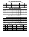
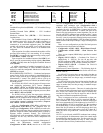
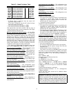
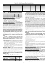
Table 67 — Mode Trip Helper Table
If the HVAC mode is HIGH HEAT:
• If Electric Heat is configured, then the control will
request the supply fan ON
• If Gas Heat is configured, then the IGC indoor fan input
controls the supply fan request
• The control will turn on Heat Relay 1 (HS1)
• The control will turn on Heat Relay 2 (HS2)
*The logic for this “low heat” override is that one stage of
heating will not be able to raise the temperature of the supply
airstream sufficient to heat the space.
HT.CF
= 3 (Staged Gas Heating Control) — As an option,
the units with gas heat can be equipped with staged gas
heat controls that will provide from 5 to 11 stages of heat
capacity. This is intended for tempering mode and tempering
economizer air when in a cooling mode and the dampers
are fully closed. Tempering can also be used during a pre-
occupancy purge to prevent low temperature air from being
delivered to the space. Tempering for staged gas will be dis-
cussed in its own section. This section will focus on heat mode
control, which ultimately is relevant to tempering, minus the
consideration of the supply air heating control point.
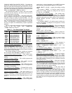
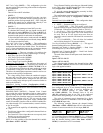
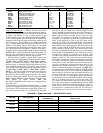
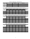
The staged gas configurations are located at the local
display under Configuration
HEAT
SG.CF. See Table 68.
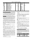
Staged Gas Heat Type (
HT.ST) — This configuration sets the
number of stages and the order that are they staged.
Max Cap Change per Cycle (
CAP.M) — This configuration
limits the maximum change in capacity per PID run time cycle.
S.Gas DB Min.dF/PID Rate (
M.R.DB) — This configuration
is a deadband minimum temperature per second rate. See
Staged Gas Heating logic below for more details.
St.Gas Temp.Dead Band (
S.G.DB) — This configuration is a
deadband delta temperature. See Staged Gas Heating logic
below for more details.
Heat Rise in dF/Sec Clamp (
RISE) — This configuration
prevents the heat from staging up when the leaving-air temper-
ature is rising too fast.
LAT Limit Config (
LAT.L) — This configuration senses
when leaving-air temperature is outside a delta temperature
band around set point and allows staging to react quicker.
Limit Switch Monitoring? (
LIM.M) — This configuration
allows the operation of the limit switch monitoring routine.
This should be set to NO as a limit switch temperature sensor is
not used with A Series units.
Limit Switch High Temp (
SW.H.T) — This configuration is
the temperature limit above which stages of heat will be
removed.
Limit Switch Low Temp (
SW.L.T) — This configuration is
the temperature limit above which no additional stages of heat
will be allowed.
Heat Control Prop. Gain (
HT.P) — This configuration is the
proportional term for the PID which runs in the HVAC mode
LOW HEAT.
Heat Control Derv. Gain (
HT.D) — This configuration is the
derivative term for the PID which runs in the HVAC mode
LOW HEAT.
Heat PID Rate Config (
HT.TM) — This configuration is the
PID run time rate.
Staged Gas Heating Logic
If the HVAC mode is HIGH HEAT:
• The supply fan for staged gas heating is controlled by the
integrated gas control (IGC) boards and, unless the
supply fan is on for a different reason, it will be con-
trolled by the IGC indoor fan input.
• Command all stages of heat ON
If the HVAC mode is LOW HEAT:
• The supply fan for staged gas heating is controlled by the
integrated gas control (IGC) boards and, unless the
supply fan is on for a different reason, it will be con-
trolled by the IGC indoor fan input.
• The unit will control stages of heat to the heating control
point (Run Status
VIEW
HT.C.P). The heating con-
trol point in a LOW HEAT HVAC mode for staged gas is
the heating supply air set point (Setpoints
SA.HT).
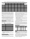
Staged Gas Heating PID Logic
— The heat control loop is a
PID (proportional/integral/derivative) design with exceptions,
overrides, and clamps. Capacity rises and falls based on set
point and supply-air temperature. When the staged gas control
is in Low Heat or Tempering Mode (HVAC mode), the algo-
rithm calculates the desired heat capacity. The basic factors that
govern the controlling method are:
• how fast the algorithm is run.
• the amount of proportional and derivative gain applied.
• the maximum allowed capacity change each time this
algorithm is run.
• deadband hold-off range when rate is low.
This routine is run once every HT.TM seconds. Every time
the routine is run, the calculated sum is added to the control
output value. In this manner, integral effect is achieved. Every
time this algorithm is run, the following calculation is
performed:
Error = HT.C.P – LAT
Error_last = error calculated previous time
P = HT.P*(Error)
D = HT.D*(Error - Error_last)
The P and D terms are overridden to zero if:
Error < S.G.DB AND Error > - S.G.DB AND D < M.R.DB
AND D > - M.R.DB. “P + D” are then clamped based on
CAP.M. This sum can be no larger or no smaller than +CAP.M
or –CAP.M.
Finally, the desired capacity is calculated:
Staged Gas Capacity Calculation = “P + D” + old Staged Gas
Capacity Calculation
NOTE: The PID values should not be modified without
approval from Carrier.
ITEM EXPANSION UNITS CCN POINT
TRIP MODE TRIP HELPER
UN.C.S Unoccup. Cool Mode Start dF UCCLSTRT
UN.C.E Unoccup. Cool Mode End dF UCCL_END
OC.C.S Occupied Cool Mode Start dF OCCLSTRT
OC.C.E Occupied Cool Mode End dF OCCL_END
TEMP Ctl.Temp RAT,SPT or Zone dF CTRLTEMP
OC.H.E Occupied Heat Mode End dF OCHT_END
OC.H.S Occupied Heat Mode Start dF OCHTSTRT
UN.H.E Unoccup. Heat Mode End dF UCHT_END
UN.H.S Unoccup. Heat Mode Start dF UCHTSTRT
HVAC the current HVAC MODE String
IMPORTANT: When gas or electric heat is used in a VAV
application with third party terminals, the HIR relay output
must be connected to the VAV terminals in the system in
order to enforce a minimum heating airflow rate. The
installer is responsible to ensure the total minimum heating
cfm is not below limits set for the equipment. Failure to do
so will result in limit switch tripping and may void warranty.