


67
RELEVANT ITEMS
The economizer’s commanded output can be found in
Outputs
ECON
ECN.C.
The configurable fire speed override for supply fan VFD is in
Configuration
SP
SP.FS.
The supply fan relay’s commanded output can be found in
Outputs
FANS
S.FAN.
The supply fan VFD’s commanded speed can be found in
Outputs
FANS
S.VFD.
Indoor Air Quality Control — The indoor air quality
(IAQ) function will admit fresh air into the space whenever
space air quality sensors detect high levels of CO
2
.
When a space or return air CO
2
sensor is connected to the
unit control, the unit’s IAQ routine allows a demand-based
control for ventilation air quantity, by providing a modulating
outside air damper position that is proportional to CO
2
level.
The ventilation damper position is varied between a minimum
ventilation level (based on internal sources of contaminants
and CO
2
levels other than from the effect of people) and the
maximum design ventilation level (determined at maximum
populated status in the building). Demand control ventilation
(DCV) is also available when the ComfortLink™ unit is con-
nected to a CCN system using ComfortID™ terminal controls.
This function also provides alternative control methods for
controlling the amount of ventilation air being admitted,
including fixed outdoor air ventilation rates (measured as cfm),
external discrete sensor switch input and externally generated
proportional signal controls.
The IAQ function requires the installation of the factory-
option economizer system. The DCV sequences also require
the connection of accessory (or field-supplied) space or return
air CO
2
sensors. Fixed cfm rate control requires the factory-
installed outdoor air cfm option. External control of the
ventilation position requires supplemental devices, including a
4 to 20 mA signal, a 10 kilo-ohm potentiometer, or a discrete
switch input, depending on the method selected. Outside air
CO
2
levels may also be monitored directly and high CO
2
economizer restriction applied when an outdoor air CO
2
sensor
is connected. (The outdoor CO
2
sensor connection requires
installation of the CEM.)
The ComfortLink control system has the capability of DCV
using an IAQ sensor. The indoor air quality (IAQ) is measured
using a CO
2
sensor whose measurements are displayed in parts
per million (ppm). The IAQ sensor can be field-installed in the
return duct. There is also an accessory space IAQ sensor that
can be installed directly in the occupied space. The sensor must
provide a 4 to 20 mA output signal and must include its own
24-v supply. The sensor connects to terminal TB5-6 and 7. Be
sure to leave the 182-ohm resistor in place on terminals 6 and 7.
OPERATION — The unit’s indoor air quality algorithm mod-
ulates the position of the economizer damper between two user
configurations depending upon the relationship between the
IAQ and the outdoor air quality (OAQ). Both of these values
can be read at the Inputs
AIR.Q submenu. The lower of these
two configurable positions is referred to as the IAQ Demand
Vent Min Position (IAQ.M), while the higher is referred to as
Economizer Minimum Position (EC.MN). The IAQ.M should
be set to an economizer position that brings in enough fresh air
to remove contaminants and CO
2
generated by sources other
than people. The EC.MN value should be set to an economizer
position that brings in enough fresh air to remove contaminants
and CO
2
generated by all sources including people. The
EC.MN value is the design value for maximum occupancy.
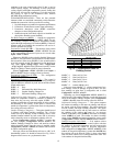
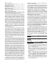
The logic that is used to control the dampers in response to
IAQ conditions is shown in Fig. 12. The ComfortLink™ con-
trols will begin to open the damper from the IAQ.M position
when the IAQ level begins to exceed the OAQ level by a
configurable amount, which is referred to as Differential Air
Quality Low Limit (DAQ.L).
If OAQ is not being measured, OAQ can be manually con-
figured. It should be set at around 400 to 450 ppm or measured
with a handheld sensor during the commissioning of the unit.
The OAQ reference level can be set using the OAQ Reference
Set Point (OAQ.U). When the differential between IAQ and
OAQ reaches the configurable Diff. Air Quality Hi Limit
(DAQ.H), then the economizer position will be EC.MN.
When the IAQ–OAQ differential is between DAQ.L and
DAQ.H, the control will modulate the damper between IAQ.M
and EC.MN as shown in Fig. 12. The relationship is a linear
relationship but other non-linear options can be used. The
damper position will never exceed the bounds specified by
IAQ.M and EC.MN during IAQ control.
If the building is occupied and the indoor fan is running and
the differential between IAQ and OAQ is less than DAQ.L, the
economizer will remain at IAQ.M. The economizer will not
close completely. The damper position will be 0 when the fan
is not running or the building is unoccupied. The damper posi-
tion may exceed EC.MN in order to provide free cooling.
The ComfortLink controller is configured for air quality
sensors which provide 4 mA at 0 ppm and 20 mA at 2000 ppm.
If a sensor has a different range, these bounds must be
reconfigured. These pertinent configurations for ranging the air
quality sensors are IQ.R.L, IQ.R.H, OQ.R.L and OQ.R.H. The
bounds represent the PPM corresponding to 4 mA (low) and
20 mA (high) for IAQ and OAQ, respectively.
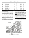
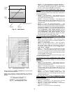
If OAQ exceeds the OAQ Lockout Value (OAQ.L), then the
economizer will remain at IAQ.M. This is used to limit the use
of outside air which outdoor air CO
2
levels are above the
OAQ.L limit. Normally a linear control of the damper vs. the
IAQ control signal can be used, but the control also supports
non-linear control. Different curves can be used based on the
Diff.AQ Responsiveness Variable (IAQ.R). See Fig. 13.
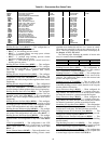
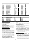
SETTING UP THE SYSTEM — The IAQ configuration op-
tions are under the Local Display Mode Configuration
IAQ.
See Table 84.
Economizer Min Position (
Configuration
IAQ
DCV.C
EC.MN) — This is the fully occupied minimum economiz-
er position.
IAQ Demand Vent Min Pos. (
Configuration
IAQ
DCV.C
IAQ.M) — This configuration will be used to set the mini-
mum damper position in the occupied period when there is no
IAQ demand.
IAQ Analog Sensor Config (
Configuration
IAQ
AQ.CF
IQ.A.C) — This is used to configure the type of
IAQ position control. It has the following options:
• IQ.A.C = 0 (No analog input). If there is no other mini-
mum position control, the economizer minimum position
will be Configuration
IAQ
DCV.C
EC.MN and
there will be no IAQ control.
• IQ.A.C = 1 (IAQ analog input). An indoor air (space or
return air) CO
2
sensor is installed. If an outdoor air CO
2
sensor is also installed, or OAQ is broadcast on the CCN,
or if a default OAQ value is used, then the unit can per-
form IAQ control.
• IQ.A.C = 2 (IAQ analog input with minimum position
override) — If the differential between IAQ and OAQ
is above Configuration
IAQ
AQ.SP
DAQ.H, the
economizer minimum position will be the IAQ override
position (Configuration
IAQ
AQ.SP
IQ.O.P).
• IQ.A.C = 3 (4 to 20 mA minimum position) — With a 4
to 20 mA signal connected to TB5-6 and 7, the econo-
mizer minimum position will be scaled linearly from 0%
(4 mA) to EC.MX (20 mA).