


41
The advantage of this offset technique is that the control can
safely enforce a vent mode without worrying about crossing set
points. Even more importantly, under CCN linkage, the
occupied heating set point may drift up and down and this
method ensures a guaranteed separation in degrees Fahrenheit
between the calling out of a heating or cooling mode at all
times.
NOTE: There is a sub-menu at the local display (Run Status
TRIP) that allows the user to see the exact trip points for
both the heating and cooling modes without having to calcu-
late them. Refer to the Cooling Mode Diagnostic Help section
on page 46 for more information.
To enter into a VAV Occupied Cool mode, the controlling
temperature must rise above [OHSP minus L.H.ON plus
L.H.OF plus V.C.O N].
To exit out of a VAV Occupied Cool Mode, the controlling
temperature must fall below [OHSP minus L.H.ON plus
L.H.OF plus V.C.O N minus V.C.OF ].
NOTE: With vent mode, it is possible to exit out of a cooling
mode during the occupied period if the return-air temperature
drops low enough. When supply-air temperature reset is not
configured, this capability will work to prevent over-cooling
the space during the occupied period.
Supply Air Set Point Control and the Staging of Compressors
— Once the control has determined that a cooling mode is in
effect, the cooling control point (Run Status
VIEW
CL.C.P) is calculated and is based upon the supply air set
point (Setpoints
SASP) plus any supply air reset being
applied (Inputs
RSET
SA.S.R).
Refer to the SumZ Cooling Algorithm section on page 46
for a discussion of how the A Series ComfortLink™ controls
manage the staging of compressors to maintain supply-air
temperature.
VAV Cool Mode Selection during the Unoccupied Period
(C.TYP = 1,2; Operating Modes
MODE
OCC=OFF)
and Space Sensor Cool Mode Selection (C.TYP=5 and 6) —
The machine control types that use this type of mode selection
are:
• C.TYP = 1 (VAV-RAT) in the unoccupied period
• C.TYP = 2 (VAV-SPT) in the unoccupied period
• C.TYP = 5 (SPT-MULTI) in both the occupied and
unoccupied period
• C.TYP = 6 (SPT-2 STG) in both the occupied and
unoccupied period
These particular control types operate differently than the
VAV types in the occupied mode in that there is both a LOW
COOL and a HIGH COOL mode. For both of these modes, the
control offers two independent set points, Setpoints
SA.LO
(for LOW COOL mode) and Setpoints
SA.HI (for HIGH
COOL mode). The occupied and unoccupied cooling set points
can be found under Setpoints.
The heat/cool set point offsets are found under Configura-
tion
D.LV.T. See Table 48.
Operating modes are under Operating Modes
MODE.
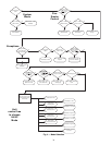
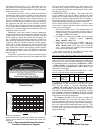
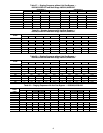
Cool Mode Evaluation Logic — The first thing the control
determines is whether the unit is in the occupied mode (OCC)
or is in the temperature compensated start mode (T.C.ST). If
the unit is occupied or in temperature compensated start mode,
the occupied cooling set point (OCSP) is used. For all other
modes, the unoccupied cooling set point (UCSP) is used. For
further discussion and simplification this will be referred to as
the “cooling set point.” See Fig. 8.
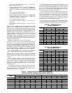
Demand Level Low Cool On Offset (L.C.ON) — This is the
cooling set point offset added to the cooling set point at which
point a Low Cool mode starts.
Demand Level High Cool On Offset (H.C.ON) — This is the
cooling set point offset added to the “cooling set point plus
L.C.ON” at which point a High Cool mode begins.
Demand Level Low Cool Off Offset (L.C.OF) — This is the
cooling set point offset subtracted from “cooling set point plus
L.C.ON” at which point a Low Cool mode ends.
NOTE: The “high cool end” trip point uses the “low cool off”
(L.C.OF) offset divided by 2.
To enter into a LOW COOL mode, the controlling tempera-
ture must rise above the cooling set point plus L.C.ON.
To enter into a HIGH COOL mode, the controlling temper-
ature must rise above the cooling set point plus L.C.ON plus
H.C.ON.
To exit out of a LOW COOL mode, the controlling temper-
ature must fall below the cooling set point plus L.C.ON minus
L.C.OF.
To exit out of a HIGH COOL mode, the controlling temper-
ature must fall below the cooling set point plus L.C.ON minus
L.C.OF/2.
Comfort Trending — In addition to the set points and offsets
which determine the trip points for bringing on and bringing
off cool modes, there are 2 configurations which work to hold
off the transitioning from a low cool to a high cool mode if the
space is cooling down quickly enough. This method is
referred to as Comfort Trending. The comfort trending config-
urations are C.T.LV and C.T.TM.
Cool Trend Demand Level (C.T.LV) — This is the change in
demand that must occur within the time period specified by
C.T.TM in order to hold off a HIGH COOL mode regardless
of demand. This is not applicable to VAV control types
(C.TYP=1 and 2) in the occupied period. As long as a LOW
COOL mode is making progress in cooling the space, the con-
trol will hold off on the HIGH COOL mode. This is especially
true for the space sensor machine control types (C.TYP = 5
and 6), because they may transition into the occupied mode
and see an immediate large cooling demand when the set
points change.
Cool Trend Time (C.T.TM) — This is the time period upon
which the cool trend demand level (C.T.LV) operates and may
hold off staging or a HIGH COOL mode. This is not applicable
to VAV control types (C.TYP=1 and 2) in the occupied period.
See the Cool Trend Demand Level section for more details.
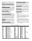
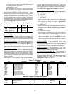
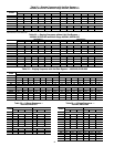
ITEM EXPANSION RANGE UNITS
CCN
POINT
DEFAULT
OCSP Occupied
Cool Setpoint
55-80 dF OCSP 75
UCSP Unoccupied
Cool Setpoint
75-95 dF UCSP 90
ITEM EXPANSION RANGE CCN POINT
MODE MODES CONTROLLING UNIT
OCC Currently Occupied ON/OFF MODEOCCP
T.C.ST Temp.Compensated Start ON/OFF MODETCST
H.C.ON
L.C. OF/2
L.C.ON
Cooling Setpoint (OCSP,UCSP)
L.C. OF
Lo Cool End
Hi Cool End
Lo Cool Start
Hi Cool Start
Fig. 8 — Cool Mode Evaluation
A48-7701