


3
GENERAL
This book contains Start-Up, Controls Operation, Trouble-
shooting and Service information for the 48/50A Series
rooftop units. See Table 1. These units are equipped with
ComfortLink™ controls.
Use this guide in conjunction with the separate installation
instructions packaged with the unit. Refer to the Wiring Dia-
grams literature for more detailed wiring information.
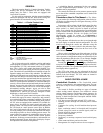
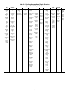
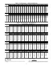
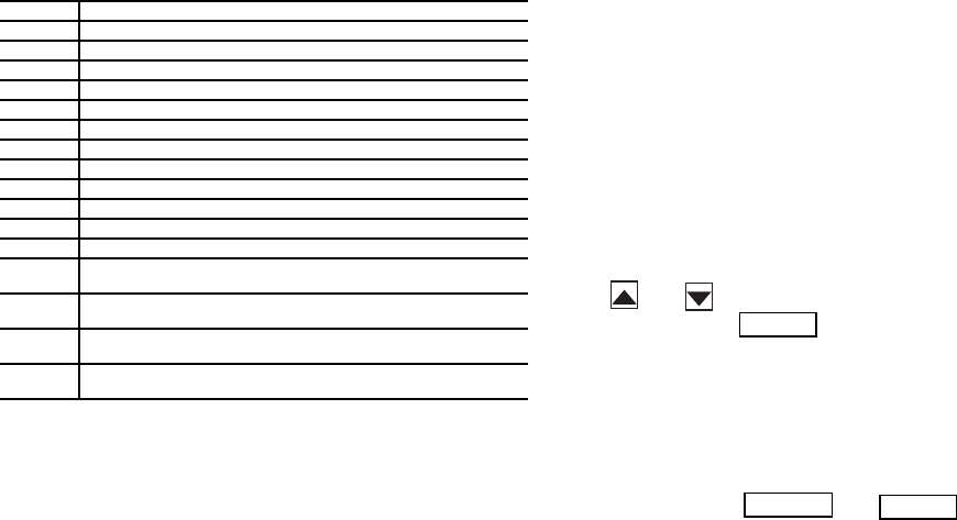
Table 1 — A Series Product Line
LEGEND
The A Series units provide ventilation, cooling, and heating
(when equipped) in variable air volume (VAV), variable volume
and temperature (VVT®), and constant volume (CV) applica-
tions. The A Series units contain the factory-installed Com-
fortLink™ control system which provides full system manage-
ment. The main base board (MBB) stores hundreds of unit con-
figuration settings and 8 time of day schedules. The MBB also
performs self diagnostic tests at unit start-up, monitors the oper-
ation of the unit, and provides alarms and alert information. The
system also contains other optional boards that are connected to
the MBB through the Local Equipment Network (LEN). Infor-
mation on system operation and status are sent to the MBB pro-
cessor by various sensors and optional boards that are located at
the unit. Access to the unit controls for configuration, set point
selection, schedule creation, and service can be done through a
unit-mounted scrolling marquee. Access can also be done
through the Carrier Comfort Network
®
(CCN) system using the
ComfortVIEW™ software, the accessory Navigator™ hand-
held display, or the System Pilot™ interface.
The ComfortLink system controls all aspects of the rooftop.
It controls the supply-fan motor, compressors, and economiz-
ers to maintain the proper temperature conditions. The controls
also cycle condenser fans to maintain suitable head pressure.
All VAV units are equipped with a standard VFD (variable fre-
quency drive) for supply fan speed control and supply duct
pressure control. The ComfortLink controls adjust the speed of
the VFD based on a static pressure sensor input. In addition,
the ComfortLink controls can raise or lower the building pres-
sure using multiple power exhaust fans controlled from econo-
mizer damper position or from a building pressure sensor. The
control safeties are continuously monitored to ensure safe oper-
ation under all conditions. Sensors include suction pressure
transducers, discharge pressure transducers, and saturated con-
densing temperature sensors which allow for display of opera-
tional pressures and saturation temperatures.
A scheduling function, programmed by the user, controls
the unit occupied/unoccupied schedule. Up to 8 different
schedules can be programmed.
The controls also allow the service person to operate a quick
test so that all the controlled components can be checked for
proper operation.
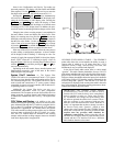
Conventions Used in This Manual — The follow-
ing conventions for discussing configuration points for the lo-
cal display (scrolling marquee or Navigator accessory) will be
used in this manual.
Point names will be written with the Mode name first, then
any sub-modes, then the point name, each separated by an
arrow symbol (). Names will also be shown in bold and
italics. As an example, the IAQ Economizer Override Position
which is located in the Configuration mode, Indoor Air Quality
Configuration sub-mode, and the Air Quality Set Points
sub-sub-mode, would be written as Configuration
IAQ
IAQ.SP
IQ.O.P. A list of point names can be found in
Appendix A.
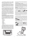
This path name will show the user how to navigate through
the local display to reach the desired configuration. The user
would scroll through the modes and submodes using the
and keys. The arrow symbol in the path name repre-
sents pressing to move into the next level of the
menu structure.
When a value is included as part of the path name, it will be
shown at the end of the path name after an equals sign. If the
value represents a configuration setting, an explanation will be
shown in parentheses after the value. As an example, Configu-
ration
IAQ
AQ.CF
IQ.AC = 1 (IAQ Analog Input).
Pressing the and keys simultaneously
at any time will display an expanded text description of the four-
character point name. The expanded description is shown in the
local display tables (Appendix A).
The CCN point names are also referenced in the local
display tables for users configuring the unit with CCN software
instead of the local display. The CCN tables are located in
Appendix B of this manual.
BASIC CONTROL USAGE
ComfortLink Controls —
The ComfortLink control
system is a comprehensive unit-management system. The con-
trol system is easy to access, configure, diagnose and trouble-
shoot.
The control is flexible, providing two types of constant
volume cooling control sequences, two variable air volume
cooling control sequences, and heating control sequences for
two-stage electric and gas systems, and for multiple-stage gas
heating, in both Occupied and Unoccupied schedule modes.
This control also manages:
• VAV duct pressure (through optional VFD), with reset
• Building pressure through two different power exhaust
schemes
• Condenser fan cycling for mild ambient head pressure
control
• Space ventilation control, in Occupied and Unoccupied
periods, using CO
2
sensors or external signals, with ven-
tilation defined by damper position
• Smoke control functions
• Occupancy schedules
• Occupancy or start/stop sequences based on third party
signals
• Alarm status and history and run time data
• Management of a complete unit service test sequence
UNIT APPLICATION
48AJ CV Unit with Gas Heat, Vertical Supply
48AK VAV Units with Gas Heat, Vertical Supply
48AW CV Unit with Gas Heat, Horizontal Supply
48AY VAV Unit with Gas Heat, Horizontal Supply
48A2 CV Unit with Gas Heat, Vertical Supply with MCHX Coil
48A3 VAV Unit with Gas Heat, Vertical Supply with MCHX Coil
48A4 CV Unit with Gas Heat, Horizontal Supply with MCHX Coil
48A5 VAV Unit with Gas Heat, Horizontal Supply with MCHX Coil
50AJ CV Unit with Optional Electric Heat, Vertical Supply
50AK VAV Unit with Optional Electric Heat, Vertical Supply
50AW CV Unit with Optional Electric Heat, Horizontal Supply
50AY VAV Unit with Optional Electric Heat, Horizontal Supply
50A2
CV Unit with Optional Electric Heat, Vertical Supply with MCHX
Coil
50A3
VAV Unit with Optional Electric Heat, Vertical Supply with MCHX
Coil
50A4
CV Unit with Optional Electric Heat, Horizontal Supply with
MCHX Coil
50A5
VAV Unit with Optional Electric Heat, Horizontal Supply with
MCHX Coil
CV — Constant Volume
MCHX — Microchannel Heat Exchanger
VAV — Variable Air Volume
ENTER
ESCAPE
ENTER