


168
APPENDIX C — VFD INFORMATION (cont)
MAIN FAN REPLACEMENT — The main cooling fan of
the VFD has a life span of about 60,000 operating hours at
maximum rated operating temperature and drive load. The
expected life span doubles for each 18 F drop in the fan
temperature (fan temperature is a function of ambient tempera-
tures and drive loads).
Fan failure can be predicted by the increasing noise from
fan bearings and the gradual rise in the heat sink temperature in
spite of heat sink cleaning. If the drive is operated in a critical
part of a process, fan replacement is recommended once these
symptoms start appearing. Replacement fans are available
from Carrier.
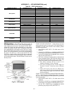
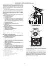
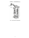
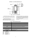
To replace the main fan for frame sizes R1 through R4,
perform the following (see Fig. D):
1. Remove power from drive.
2. Remove drive cover.
3. For frame sizes R1 and R2, press together the retaining
clips on the fan cover and lift. For frame sizes R3 and R4,
press in on the lever located on the left side of the fan
mount, and rotate the fan up and out.
4. Disconnect the fan cable.
5. Install the new fan by reversing Steps 2 to 4.
6. Restore power.
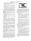
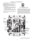
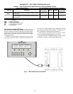
To replace the main fan for frame sizes R5 and R6, perform
the following (see Fig. E):
1. Remove power from drive.
2. Remove the screws attaching the fan.
3. Disconnect the fan cable.
4. Install the fan in reverse order.
5. Restore power.
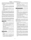
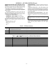
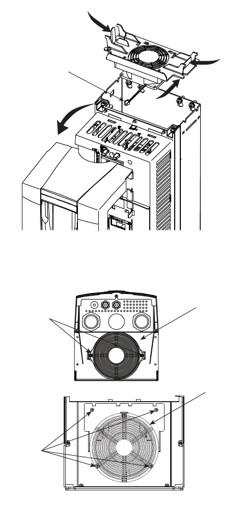
INTERNAL ENCLOSURE FAN REPLACEMENT — The
VFD IP 54 / UL Type 12 enclosures have an additional internal
fan to circulate air inside the enclosure.
To replace the internal enclosure fan for frame sizes R1 to
R4, perform the following (see Fig. F):
1. Remove power from drive.
2. Remove the front cover.
3. The housing that holds the fan in place has barbed retain-
ing clips at each corner. Press all four clips toward the
center to release the barbs.
4. When the clips/barbs are free, pull the housing up to re-
move from the drive.
5. Disconnect the fan cable.
6. Install the fan in reverse order, noting the following: the
fan airflow is up (refer to arrow on fan); the fan wire
harness is toward the front; the notched housing barb is
located in the right-rear corner; and the fan cable connects
just forward of the fan at the top of the drive.
To replace the internal enclosure fan for frame sizes R5 or
R6, perform the following:
1. Remove power from drive.
2. Remove the front cover.
3. Lift the fan out and disconnect the cable.
4. Install the fan in reverse order.
5. Restore power.
CONTROL PANEL CLEANING — Use a soft damp cloth
to clean the control panel. Avoid harsh cleaners which could
scratch the display window.
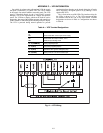
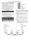
BATTERY REPLACEMENT — A battery is only used in as-
sistant control panels that have the clock function available and
enabled. The battery keeps the clock operating in memory
during power interruptions. The expected life for the battery is
greater than ten years. To remove the battery, use a coin to
rotate the battery holder on the back of the control panel.
Replace the battery with type CR2032.
3
3
4
2
3
2
Bottom View (R5)
2
3
Bottom View (R6)
Fig. D — Main Fan Replacement
(Frame Sizes R1-R4)
Fig. E — Main Fan Replacement
(Frame Sizes R5 and R6)
A39-2922
A48-7714
A48-7715