


39
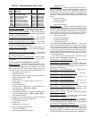
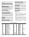
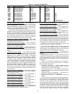
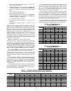
Table 47 — Cooling Configuration
Capacity Threshold Adjust (
Z.GN) — This configuration is
used for units using the “SumZ” algorithm for cooling capacity
control (Configuration
UNIT
C.TYP = 1, 2, 3 or 5). The
configuration affects the cycling rate of the cooling stages by
raising or lowering the threshold that demand must rise above
in order to add or subtract a stage of cooling.
Normally this configuration should not require any tuning or
adjustment. If there is an application where the unit may be sig-
nificantly oversized and there are indications of high compres-
sor cycles, then the Capacity Threshold Adjust (Z.GN) can be
used to adjust the overall logic gain. Normally this is set to 1.0,
but it can be adjusted from 0.5 to 4.0. As the value of Z.GN is
increased, the cycling of cooling stages will be slowed.
Compressor Lockout Temperature (
MC.LO) — This config-
uration is the outdoor air temperature setting below which
mechanical cooling is locked out.
Fan-Off Delay, Mech Cool (
C.FOD) — After a mechanical
cooling cycle has ended, this is the delay in seconds that the
supply fan will continue to operate.
Min. Load Valve (HGBP)? (
MLV) — This configuration in-
structs the control as to whether a minimum load valve has
been installed and will be controlled by the compressor staging
routine.
MotorMaster Control? (
M.M.) — The condenser fan staging
control for the unit is managed directly by the ComfortLink™
controls. There is no physical Motormaster
®
device in the
standard unit. The standard unit is capable of mechanical
cooling operation down to 32 F outdoor temperature. With the
addition of accessory Motormaster V speed control on the stage
1 condenser fan(s), mechanical cooling operation down to
–20 F outdoor temperature is possible. The accessory Motor-
master V speed control is a completely self-contained device
and is not managed by the unit’s ComfortLink controller. The
Motormaster control configuration (M.M.) only applies to the
060 size RTPF units. On 060 size RTPF units with accessory
Motormaster V speed control installed, this configuration must
be set to YES. See Head Pressure Control section, page 49, for
more information.
Head Pressure Set Point (
HPSP) — This is the head pressure
set point used by the ComfortLink control during condenser
fan, head pressure control.
Enable Compressor A1 (
A1.EN) — This configuration is
used to disable the A1 compressor in case of failure.
Enable Compressor A2 (
A2.EN) — This configuration is
used to disable the A2 compressor in case of failure.
Enable Compressor B1 (
B1.EN) — This configuration is
used to disable the B1 compressor in case of failure.
Enable Compressor B2 (
B2.EN) — This configuration is
used to disable the B2 compressor in case of failure.
CSB A1 Feedback Alarm (
CS.A1) — This configuration is
used to enable or disable the compressor A1 feedback alarm.
This configuration must be enabled at all times.
CSB A2 Feedback Alarm (
CS.A2) — This configuration is
used to enable or disable the compressor A2 feedback alarm.
This configuration must be enabled at all times.
CSB B1 Feedback Alarm (
CS.B1) — This configuration is
used to enable or disable the compressor B1 feedback alarm.
This configuration must be enabled at all times.
CSB B2 Feedback Alarm (
CS.B2) — This configuration is
used to enable or disable the compressor B2 feedback alarm.
This configuration must be enabled at all times.
Reverse Rotation Verified? (
REV.R) — If this configuration
is set to NO, then after a power up, in the normal run mode, the
control will check the suction pressure on the first circuit that is
energized after 5 seconds of run time. If the control does not
see a sufficient decrease in suction pressure over the first 5 sec-
onds, mechanical cooling will be shut down, and an alarm will
be generated (A140). This alarm requires a manual reset.
If the unit is in the Service Test mode, the test will be
performed any time a compressor is energized.
Once it has been verified that power to the rooftop and
compressors has been applied correctly and the compressors
start up normally, this configuration can be set to YES in order
to prevent the reverse rotation check from occurring.
High SST Alert Delay Time (
H.SST) — This option allows
the high saturated suction temperature alert timing delay to be
adjusted.
COMPRESSOR SAFETIES — The 48/50A Series units with
ComfortLink™ controls include a compressor protection board
(CSB) that protects the operation of each of the compressors.
These boards sense the presence or absence of current to each
compressor.
If there is a command for a compressor to run and there is
no current, then one of the following safeties or conditions
have turned the compressor off:
• Compressor overcurrent — Smaller compressors have
internal line breaks and larger compressors have a dedicated
circuit breaker for overcurrent protection.
• Compressor short circuit — the compressor circuit breaker
that provides short circuit protection has tripped then there
will not be current.
• Compressor motor over temperature — the internal line-
break or over temperature switch has opened.
• High-pressure switch trip — High-pressure switch has
opened.
Alarms will also occur if the current sensor board malfunc-
tions or is not properly connected to its assigned digital input. If
the compressor is commanded OFF and the Current Sensor
reads ON, an alert is generated. This will indicate that a com-
pressor contactor has failed closed. In this case, a special mode
“Compressor Stuck on Control” will be enabled and all other
compressors will be turned off and an alarm enabled to indicate
that service is required. Indoor and outdoor fans will continue
to operate. The first outdoor fan stage is turned on immediately.
The second fan stage will turn on when outdoor-air
ITEM EXPANSION RANGE UNITS CCN POINT DEFAULT
COOL COOLING CONFIGURATION
Z.GN Capacity Threshold Adjst –10 - 10 Z_GAIN 1
MC.LO Compressor Lockout Temp –20 - 55 dF OATLCOMP 40
C.FOD Fan-Off Delay, Mech Cool 0-600 sec COOL_FOD 60
MLV Min. Load Valve (HGBP)? Yes/No MLV_SEL No
M.M. Motor Master Control ? Yes/No MOTRMAST No
HPSP Head Pressure Setpoint 80 - 150 dF HPSP 113
A1.EN Enable Compressor A1 Enable/Disable CMPA1ENA Enable
A2.EN Enable Compressor A2 Enable/Disable CMPA2ENA Enable
B1.EN Enable Compressor B1 Enable/Disable CMPB1ENA Enable
B2.EN Enable Compressor B2 Enable/Disable CMPB2ENA Enable
CS.A1 CSB A1 Feedback Alarm Enable/Disable CSB_A1EN Enable
CS.A2 CSB A2 Feedback Alarm Enable/Disable CSB_A2EN Enable
CS.B1 CSB B1 Feedback Alarm Enable/Disable CSB_B1EN Enable
CS.B2 CSB B2 Feedback Alarm Enable/Disable CSB_B2EN Enable
REV.R Rev. Rotation Verified? Yes/No REVR_VER No
H.SST Hi SST Alert Delay Time 5 - 30 min HSSTTIME 10 (48/50AJ,AK,AW,AY)
20 (48/50A2,A3,A4,A5)