


5
Items in the Configuration and Service Test modes are
password protected. The display will flash PASS and WORD
when required. Use the and arrow keys to enter the
four digits of the password. The default password is 1111.
Pressing the and keys simultaneously
will scroll an expanded text description across the display indi-
cating the full meaning of each display point. Pressing the
and keys when the display is blank
(MODE LED level) will return the display to its default menu
of rotating AUTO VIEW display items. In addition, the pass-
word will need to be entered again before changes can be made.
Changing item values or testing outputs is accomplished in
the same manner. Locate and display the desired item. If the
display is in rotating auto-view, press the key to stop
the display at the desired item. Press the key again so
that the item value flashes. Use the arrow keys to change the
value of state of an item and press the key to accept
it. Press the key and the item, value or units display
will resume. Repeat the process as required for other items.
If the user needs to force a variable, follow the same process
as when editing a configuration parameter. A forced variable
will be displayed with a blinking “f” following its value. For
example, if supply fan requested (FAN.F) is forced, the display
shows “YESf”, where the “f” is blinking to signify a force on
the point. Remove the force by selecting the point that is forced
with the key and then pressing the and ar-
row keys simultaneously.
Depending on the unit model, factory-installed options and
field-installed accessories, some of the items in the various
Mode categories may not apply.
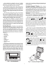
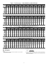
System Pilot™ Interface — The System Pilot
(33PILOT-01) device is a component of Carrier’s 3V™ system
and serves as a user-interface and configuration tool for all Car-
rier communicating devices. The System Pilot device can be
used to install and commission a 3V zoning system, linkage
compatible air source, universal controller, and all other devic-
es operating on the CCN system.
Additionally, the System Pilot device can serve as a
wall-mounted temperature sensor for space temperature
measurement. The occupant can use the System Pilot device to
change set points. A security feature is provided to limit access
of features for unauthorized users. See Fig. 3 for System Pilot
details.
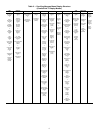
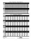
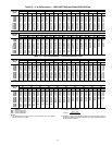
CCN Tables and Display — In addition to the unit-
mounted scrolling marquee display, the user can also access the
same information through the CCN tables by using the Service
Tool or other CCN programs. Details on the CCN tables are
summarized in Appendix B. The variable names used for the
CCN tables and the scrolling marquee tables may be different
and more items are displayed in the CCN tables. As a refer-
ence, the CCN variable names are included in the scrolling
marquee tables and the scrolling marquee names are included
in the local display tables in Appendix B.
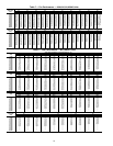
GENERICS STATUS DISPLAY TABLE — The GENERICS
points table allows the service/installer the ability to create a
custom table in which up to 20 points from the 5 CCN
categories (Points, Config, Service-Config, Set Point, and
Maintenance) may be collected and displayed.
In the Service-Config table section, there is a table named
“generics”. This table contains placeholders for up to 20 CCN
point names and allows the user to decide which points are dis-
played in the GENERICS points table under the local display.
Each one of these placeholders allows the input of an 8-character
ASCII string. Using a CCN interface, enter the Edit mode for the
Service-Config table “generics” and enter the CCN name for
each point to be displayed in the custom points table in the order
they will be displayed. When done entering point names, down-
load the table to the rooftop unit control.
ENTER
ESCAPE
ENTER
ESCAPE
ENTER
ENTER
ENTER
ENTER
ESCAPE
ENTER
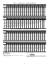
IMPORTANT: The computer system software
(ComfortVIEW™, Service Tool, etc.) that is used to
interact with CCN controls always saves a template of
items it considers as static (e.g., limits, units, forcibil-
ity, 24-character text strings, and point names) after
the software uploads the tables from a control. There-
after, the software is only concerned with run time
data like value and hardware/force status. With this in
mind, it is important that anytime a change is made to
the Service-Config table “generics” (which in turn
changes the points contained in the GENERICS point
table), that a complete new upload be performed. This
requires that any previous table database be
completely removed first. Failure to do this will not
allow the user to display the new points that have been
created and the CCN interface will have a different
table database than the unit control.
SCROLL
+
-
NAVIGATE/
EXIT
MODIFY/
SELECT
PAGE
Fig. 3 — System Pilot™ User Interface
A33-1050