


30
However, it is important to note that the user can leave a
Service Test mode to view any of the local display modes and
the control will remain in the Service Test mode.
Independent Outputs — The INDP sub-mode items
can be turned on and off regardless of the other category states.
For example, the alarm relay can be forced on in the INDP
sub-mode and will remain on if compressor relays are request-
ed in the COOL sub-mode.
Fans in Service Test Mode — Upon entering the
FANS sub-mode, the user will be able to turn the supply fan on
and off, set the supply fan VFD speed, and turn the condenser
fans on and off.
Cooling in Service Test Mode — The COOL sub-
mode offers different cooling service tests.
The user has manual relay control of individual compres-
sors. If the user energizes mechanical cooling, the supply fan
and the outdoor fans will be started automatically. During
mechanical cooling, the unit will protect itself. Compressor
diagnostics are active, monitoring for high discharge pressure,
low suction pressure, etc. The user can also turn the hot gas
bypass valve on and off.
NOTE: It is crucial that proper compressor rotation be verified
during the service test. Each compressor must be tested
individually. After starting each compressor, the control will
check the suction pressure after 5 seconds of run time. If the
control does not see a sufficient decrease in suction pressure
after 5 seconds, mechanical cooling will be shut down, and an
alarm will be generated (A140). This alarm requires a manual
reset. If this alarm occurs, do not attempt a restart of the
compressor and do not attempt to start any other compressors
until the wiring to the unit has been corrected.
Heating in Service Test Mode — If unit has a ther-
mostat connected (C.TYP = 3 or 4), install the RED jumper
wires between TB4, terminals R (1), W2 (3) and W1 (4). Ter-
minal block TB4 is located in the unit control box. Remember
to disconnect these jumpers when Test Mode is completed. The
Heat Test Mode sub-mode will offer automatic fan start-up if
the unit is not a gas heat unit. On gas heat units, the IGC feed-
back from the gas control units will bring the fan on as
required.
Within this sub-mode, the user has control of heat relays 1
to 6. The user can also turn on the requested heat stage.
NOTE: When service test has been completed, if unit has a
thermostat connected (C.TYP = 3 or 4), remove the RED
jumper wires at TB4, terminals R (1), W2 (3) and W1 (4).
Terminal block TB4 is located in the unit control box. Store
these jumpers in the unit control box for future use.
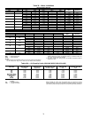
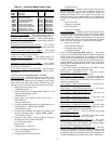
Table 41 — Service Test
ITEM EXPANSION RANGE UNITS POINT WRITE STATUS
TEST Service Test Mode ON/OFF MAN_CTRL
STOP Local Machine Disable YES/NO UNITSTOP config
S.STP Soft Stop Request YES/NO SOFTSTOP forcible
FAN.F Supply Fan Request YES/NO SFANFORC forcible
F.4.CH 4 in. Filter Change Mode YES/NO FILT4CHG
INDP TEST INDEPENDENT OUTPUTS
ECON Economizer Act.Cmd.Pos. ECONCTST
E.PWR Economizer Power Test ECONPTST
E.CAL Calibrate the Economizer? ECON_CAL
E.VFD Exhaust Fan VFD Speed 0-100 % EFAN_VFD
PE.A Power Exhaust Relay A PE_A_TST
PE.B Power Exhaust Relay B PE_B_TST
PE.C Power Exhaust Relay C PE_C_TST
H.I.R Heat Interlock Relay ON/OFF HIR_TST
ALRM Remote Alarm/Aux Relay ON/OFF ALRM_TST
FANS TEST FANS
S.FAN Supply Fan Relay ON/OFF SFAN_TST
S.VFD Supply Fan VFD Speed 0-100 % SGVFDTST
CD.F.A Condenser Fan Circuit A ON/OFF CNDA_TST
CD.F.B Condenser Fan Circuit B ON/OFF CNDB_TST
COOL TEST COOLING
A1 Compressor A1 Relay ON/OFF CMPA1TST
A2 Compressor A2 Relay ON/OFF CMPA2TST
MLV Min. Load Valve (HGBP) ON/OFF MLV_TST
B1 Compressor B1 Relay ON/OFF CMPB1TST
B2 Compressor B2 Relay ON/OFF CMPB2TST
HEAT TEST HEATING
HT.ST Requested Heat Stage 0-MAX HTST_TST
HT.1 Heat Relay 1 ON/OFF HS1_TST
HT.2 Heat Relay 2 ON/OFF HS2_TST
HT.3 Relay 3 W1 Gas Valve 2 ON/OFF HS3_TST
HT.4 Relay 4 W2 Gas Valve 2 ON/OFF HS4_TST
HT.5 Relay 5 W1 Gas Valve 3 ON/OFF HS5_TST
HT.6 Relay 6 W2 Gas Valve 3 ON/OFF HS6_TST