


46
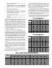
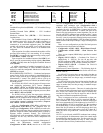
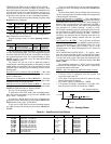
COOLING MODE DIAGNOSTIC HELP — To quickly de-
termine the current trip points for the cooling modes, the Run
Status sub-menu at the local display allows the user to view the
calculated start and stop points for both the cooling and heating
trip points. The following sub-menu can be found at the local
display under Run Status
TRIP. See Table 61.
The controlling temperature is “TEMP” and is in the middle
of the table for easy reference. The HVAC mode can also be
viewed at the bottom of the table.
SUMZ COOLING ALGORITHM — The SumZ cooling algo-
rithm is an adaptive PID which is used by the control whenever
more than 2 stages of cooling are present (C.TYP = 1,2,3, and
5). This section will describe its operation and define its param-
eters. It is generally not necessary to modify parameters in this
section. The information is presented primarily for reference
and may be helpful for troubleshooting complex operational
problems.
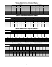
The only configuration parameter for the SumZ algorithm is
located at the local display under Configuration
COOL
Z.GN. See Table 47.
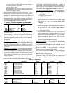
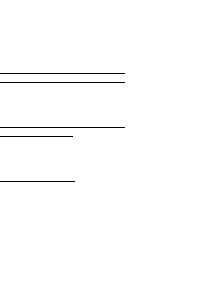
Table 61 — Run Status Mode Trip Helper
Capacity Threshold Adjust (
Z.GN) — This configuration is
used on units using the “SumZ” algorithm for cooling capacity
control (Configuration
UNIT
C.TYP = 1, 2, 3 and 5). It
affects the cycling rate of the cooling stages by raising or
lowering the threshold that capacity must overcome in order to
add or subtract a stage of cooling.
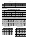
The cooling algorithm’s run-time variables are located at
the local display under Run Status
COOL. See Table 62.
Current Running Capacity (
C.CAP) — This variable repre-
sents the amount of capacity in percent that is currently
running.
Current Cool Stage (
CUR.S) — This variable represents the
cool stage currently running.
Requested Cool Stage (
REQ.S) — This variable represents
the cool stage currently requested by the control.
Maximum Cool Stages (
MAX.S) — This variable is the max-
imum number of cooling stages the control is configured for
and capable of controlling.
Active Demand Limit (
DEM.L) — If demand limit is active,
this variable will represent the amount of capacity that the
control is currently limited to.
Capacity Load Factor (
SMZ) — This factor builds up or
down over time (–100 to +100) and is used as the means of
adding or subtracting a cooling stage during run time. It is a
normalized representation of the relationship between “Sum”
and “Z”.
Next Stage EDT Decrease (
ADD.R) — This variable repre-
sents (if adding a stage of cooling) how much the temperature
should drop in degrees depending on the R.PCT calculation
and exactly how much additional capacity is to be added.
ADD.R = R.PCT * (C.CAP — capacity after adding a cooling
stage)
For example: If R.PCT = 0.2 and the control would be
adding 20% cooling capacity by taking the next step up,
0.2 times 20 = 4 F (ADD.R).
Next Stage EDT Increase (
SUB.R) — This variable repre-
sents (if subtracting a stage of cooling) how much the
temperature should rise in degrees depending on the R.PCT
calculation and exactly how much capacity is to be subtracted.
SUB.R = R.PCT * (C.CAP — capacity after subtracting a
cooling stage)
For Example: If R.PCT = 0.2 and the control would be sub-
tracting 30% capacity by taking the next step down, 0.2 times
–30 = –6 F (SUB.R)
Rise Per Percent Capacity (
R.PCT) — This is a real time cal-
culation that represents the amount of degrees of drop/rise
across the evaporator coil versus percent of current running
capacity.
R.PCT = (MAT – EDT)/ C.CAP
Cap Deadband Subtracting (
Y.MIN) — This is a control vari-
able used for Low Temp Override (L.TMP) and Slow Change
Override (SLOW).
Y.MIN = -SUB.R*0.4375
Cap Deadband Adding (
Y.PLU) — This is a control variable
used for High Temp Override (H.TMP) and Slow Change
Override (SLOW).
Y.PLU = -ADD.R*0.4375
Cap Threshold Subtracting (
Z.MIN) — This parameter is
used in the calculation of SumZ and is calculated as follows:
Z.MIN = Configuration
COOL
Z.GN * (–10 + (4*
(–SUB.R))) * 0.6
Cap Threshold Adding (
Z.PLU) — This parameter is used in
the calculation of SumZ and is calculated as follows:
Z.PLU = Configuration
COOL
Z.GN * (10 + (4*
(–ADD.R))) * 0.6
High Temp Cap Override (
H.TMP) — If stages of mechani-
cal cooling are on and the error is greater than twice Y.PLU,
and the rate of change of error is greater than 0.5F per minute,
then a stage of mechanical cooling will be added every 30 sec-
onds. This override is intended to react to situations where the
load rapidly increases.
Low Temp Cap Override (
L.TMP) — If the error is less than
twice Y.MIN, and the rate of change of error is less than
–0.5F per minute, then a mechanical stage will be removed
every 30 seconds. This override is intended to quickly react to
situations where the load is rapidly reduced.
Pull Down Cap Override (
PULL) — If the error from set
point is above 4F, and the rate of change is less than –1F per
minute, then pulldown is in effect, and “SUM” is set to 0. This
keeps mechanical cooling stages from being added when the
error is very large, but there is no load in the space. Pulldown
for units is expected to rarely occur, but is included for the rare
situation when it is needed. Most likely pulldown will occur
when mechanical cooling first becomes available shortly after
the control goes into an occupied mode (after a warm unoccu-
pied mode).
ITEM EXPANSION UNITS
CCN
POINT
TRIP MODE TRIP HELPER
UN.C.S Unoccup. Cool Mode Start dF UCCLSTRT
UN.C.E Unoccup. Cool Mode End dF UCCL_END
OC.C.S Occupied Cool Mode Start dF OCCLSTRT
OC.C.E Occupied Cool Mode End dF OCCL_END
TEMP Ctl.Temp RAT,SPT or Zone dF CTRLTEMP
OC.H.E Occupied Heat Mode End dF OCHT_END
OC.H.S Occupied Heat Mode Start dF OCHTSTRT
UN.H.E Unoccup. Heat Mode End dF UCHT_END
UN.H.S Unoccup. Heat Mode Start dF UCHTSTRT
HVAC the current HVAC MODE String