


74
Discharge Pressure Circuit A Trim (
DP.A.T) — This vari-
able is used to adjust the discharge pressure sensor reading for
circuit A. The sensor reading can be adjusted ± 50 psig to
match the actual measured pressure. Used on 48/
50A2,A3,A4,A5 units only.
Discharge Pressure Circuit B Trim (
DP.B.T) — This vari-
able is used to adjust the discharge pressure sensor reading for
circuit B. The sensor reading can be adjusted ± 50 psig to
match the actual measured pressure. Used on 48/
50A2,A3,A4,A5 units only.
4 to 20 mA Inputs
— There are a number of 4 to 20 mA in-
puts which may be calibrated. These inputs are located in
Inputs
4-20. They are:
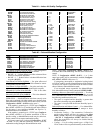
• SP.M.T — static pressure milliamp trim
• BP.M.T — building pressure milliamp trim
• OA.M.T — outside air cfm milliamp trim
• RA.M.T — return air cfm milliamp trim
• SA.M.T — supply air cfm milliamp trim
Discrete Switch Logic Configuration — The SW.LG
submenu is used to configure the normally open/normally closed
settings of switches and inputs. This is used when field-supplied
switches or input devices are used instead of Carrier devices. The
normally open or normally closed setting may be different on a
field-supplied device. These points are used to match the control
logic to the field-supplied device.
The defaults for this switch logic section will not normally
need changing. However, if a field-installed switch is used that
is different from the Carrier switch, these settings may need
adjustment.
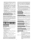
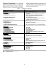
Settings for switch logic are found at the local displays
under the Configuration
SW.LG submenu. See Table 89.
Filter Status Input — Clean (
FTS.L) — The filter status in-
put for clean filters is set for normally open. If a field-supplied
filter status switch is used that is normally closed for a clean
filter, change this variable to closed.
IGC Feedback — Off (
IGC.L) — The input for IGC feed-
back is set for normally open for off. If a field-supplied IGC
feedback switch is used that is normally closed for feedback
off, change this variable to closed.
Remote Switch — Off (
RMI.L) — The remote switch is set
for normally open when off. If a field-supplied control switch
is used that is normally closed for an off signal, change this
variable to closed.
Economizer Switch — No (
ECS.L) — The economizer
switch is set for normally open when low. If a field-supplied
economizer switch is used that is normally closed when low,
change this variable to closed.
Fan Status Switch — Off (
SFS.L) — The fan status switch
input is set for normally open for off. If a field-supplied fan
status switch is used that is normally closed, change this
variable to closed.
Demand Limit Switch 1 — Off (
DL1.L) — The demand
limit switch no. 1 input is set for normally open for off. If a
field-supplied demand limit switch is used that is normally
closed, change this variable to closed.
Demand Limit Switch 2/Dehumidify — Off (
DL2.L) —
The demand limit switch no. 2 input is set for normally open
for off. If a field-supplied demand limit switch is used that is
normally closed, change this variable to closed.
IAQ Discrete Input — Low (
IAQ.L) — The IAQ discrete in-
put is set for normally open when low. If a field-supplied IAQ
discrete input is used that is normally closed, change this vari-
able to closed.
Fire Shutdown — Off (
FSD.L) — The fire shutdown input is
set for normally open when off. If a field-supplied fire shut-
down input is used that is normally closed, change this variable
to closed.
Pressurization Switch — Off (
PRS.L) — The pressurization
input is set for normally open when off. If a field-supplied pres-
surization input is used that is normally closed, change this
variable to closed.
Evacuation Switch — Off (
EVC.L) — The evacuation input is
set for normally open when off. If a field-supplied evacuation in-
put is used that is normally closed, change this variable to closed.
Smoke Purge — Off (
PRG.L) — The smoke purge input is set
for normally open when off. If a field-supplied smoke purge in-
put is used that is normally closed, change this variable to closed.
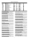
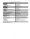
Display Configuration — The DISP submenu is used
to configure the local display settings. A list is shown in
Table 90.
Test Display LEDs (
TEST) — This is used to test the opera-
tion of the ComfortLink™ display.
Metric Display (
METR) — This variable is used to change
the display from English units to Metric units.
Language Selection (
LANG) — This variable is used to
change the language of the ComfortLink display. At this time,
only English is available.
Password Enable (
PAS.E) — This variable enables or dis-
ables the use of a password. The password is used to restrict
use of the control to change configurations.
Service Password (
PASS) — This variable is the 4-digit nu-
meric password that is required if enabled.
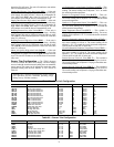
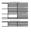
Remote Control Switch Input — The remote switch
input is located on the ECB-1 board and connected to TB6 ter-
minals 1 and 3. The switch can be used for several remote con-
trol functions. See Table 91.
Remote Input State
(Inputs
GEN.I
REMT) — This is
the actual real time state of the remote input.
Remote Switch Config
(Configuration
UNIT
RM.CF)
— This is the configuration that allows the user to assign dif-
ferent types of functionality to the remote discrete input.
• 0 — NO REMOTE SW — The remote switch will not be
used.
• 1 — OCC-UNOCC SW — The remote switch input will
control the occupancy state. When the remote switch
input is ON, the unit will forced into the occupied mode.
When the remote switch is OFF, the unit will be forced
into the unoccupied mode.
• 2 — STRT/STOP — The remote switch input will start
and stop the unit. When the unit is commanded to stop,
any timeguards in place on compressors will be honored
first. When the remote switch is ON, the unit will be
commanded to stop. When the remote switch is OFF the
unit will be enabled to operate.
• 3 — OVERRIDE SW — The remote switch can be used
to override any internal or external time schedule being
used by the control and force the unit into an occupied
mode when the remote input state is ON. When the
remote switch is ON, the unit will be forced into an occu-
pied state. When the remote switch is OFF, the unit will
use its internal or external time schedules.
IMPORTANT: Many of the switch inputs to the con-
trol can be configured to operate as normally open or
normally closed.