


54
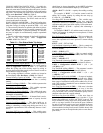
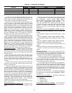
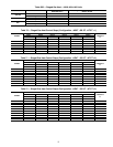
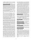
Table 68 — Staged Gas Configuration
*Some configurations are model number dependent.
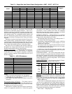
Staged Gas Heat Staging — Different unit sizes will control
heat stages differently based on the amount of heating capacity
included. These staging patterns are selected based on the mod-
el number. The selection of a set of staging patterns is con-
trolled via the heat stage type configuration parameter (HT.ST).
As the heating capacity rises and falls based on demand, the
staged gas control logic will stage the heat relay patterns up and
down, respectively. The Heat Stage Type configuration selects
one of 4 staging patterns that the stage gas control will use. In
addition to the staging patterns, the capacity for each stage
is also determined by the staged gas heating PID control. There-
fore, choosing the heat relay outputs is a function of the capaci-
ty desired, the heat staging patterns based on the heat stage type
(HT.ST) and the capacity presented by each staging pattern. As
the staged gas control desired capacity rises, it is continually
checked against the capacity of the next staging pattern.
When the desired capacity is greater than or equal to the
capacity of the next staging pattern, the next heat stage is select-
ed (Run Status
VIEW
HT.ST = Run Status
VIEW
HT.ST + 1). Similarly, as the capacity of the control drops, the
desired capacity is continually checked against the next lower
stage. When the desired capacity is less than or equal to the next
lower staging pattern, the next lower heat stage pattern is select-
ed (Run Status
VIEW
HT.ST = Run Status
VIEW
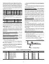
HT.ST - 1). The first two staged gas heat outputs are located on
the MBB board and outputs 3, 4, 5, and 6 are located on
the SCB board. These outputs are used to produce 5 to 11 stages
as shown in Tables 69A and 69B. The heat stage selected (Run
Status
VIEW
HT.ST) is clamped between 0 and the maxi-
mum number of stages possible (Run Sta-
tus
VIEW
H.MAX) for the chosen set of staging patterns.
See Tables 70-73.
INTEGRATED GAS CONTROL BOARD LOGIC — All gas
heat units are equipped with one or more integrated gas control
(IGC) boards. This board provides control for the ignition sys-
tem for the gas heat sections. On size 020-050 low heat units
there will be one IGC board. On size 020-050 high heat units
and 051 and 060 low heat units there are two IGC boards. On
size 051 and 060 high heat units there are three IGC boards.
When a call for gas heat is initiated, power is sent to W on the
IGC boards. For standard 2-stage heat, all boards are wired
in parallel. For staged gas heat, each board is controlled sepa-
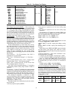
rately. When energized, an LED on the IGC board will be
turned on. See Table 74 for LED explanations. Each board will
ensure that the rollout switch and limit switch are closed. The
induced-draft motor is then energized. When the speed of the
motor is proven with the Hall Effect sensor on the motor, the
ignition activation period begins. The burners ignite within
5 seconds. If the burners do not light, there is a 22-second delay
before another 5-second attempt is made. If the burners still do
not light, this sequence is repeated for 15 minutes. After
15 minutes have elapsed and the burners have not ignited then
heating is locked out. The control will reset when the request
for W (heat) is temporarily removed. When ignition occurs, the
IGC board will continue to monitor the condition of the rollout
switch, limit switches, Hall Effect sensor, and the flame sensor.
Forty-five seconds after ignition has occurred, the IGC will
request that the indoor fan be turned on. The IGC fan output
(IFO) is connected to the indoor fan input on the MBB which
will indicate to the controls that the indoor fan should be turned
on (if not already on). If for some reason the overtemperature
limit switch trips prior to the start of the indoor fan blower, on
the next attempt the 45-second delay will be shortened by
5 seconds. Gas will not be interrupted to the burners and heat-
ing will continue. Once modified, the fan delay will not change
back to 45 seconds unless power is reset to the control. The
IGC boards only control the first stage of gas heat on each gas
valve. The second stages are controlled directly from the MBB
board. The IGC board has a minimum on-time of 1 minute. In
modes such as Service Test where long minimum on times are
not enforced, the 1-minute timer on the IGC will still be fol-
lowed and the gas will remain on for a minimum of 1 minute.
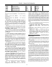
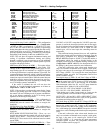
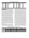
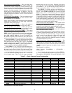
Table 69A — Staged Gas Heat — 48AJ,AK,AW,AY Units
ITEM EXPANSION RANGE UNITS CCN POINT DEFAULTS
SG.CF STAGED GAS CONFIGS
HT.ST Staged Gas Heat Type 0 - 4 HTSTGTYP 0*
CAP.M Max Cap Change per Cycle 5 - 45 HTCAPMAX 45*
M.R.DB S.Gas DB min.dF/PID Rate 0 - 5 HT_MR_DB 0.5
S.G.DB St.Gas Temp. Dead Band 0 - 5 ^F HT_SG_DB 2
RISE Heat Rise dF/sec Clamp 0.05 - 0.2 HTSGRISE 0.06
LAT.L LAT Limit Config 0 - 20 ^F HTLATLIM 10
LIM.M Limit Switch Monitoring? Yes/No HTLIMMON Yes
SW.H.T Limit Switch High Temp 110 - 180 dF HT_LIMHI 170*
SW.L.T Limit Switch Low Temp 100 - 170 dF HT_LIMLO 160*
HT.P Heat Control Prop. Gain 0 - 1.5 HT_PGAIN 1
HT.D Heat Control Derv. Gain 0 - 1.5 HT_DGAIN 1
HT.TM Heat PID Rate Config 60 - 300 sec HTSGPIDR 90
UNIT SIZE HEAT CAPACITY
UNIT MODEL NO.
POSITION NO. 5
Configuration
HEAT
SG.CF
HT.ST
ENTRY VALUE
020-035
Low S 1 = 5 STAGE
High T 2 = 7 STAGE
036-050
Low S 1 = 5 STAGE
High T 1 = 5 STAGE
051,060
Low S 4 = 11 STAGE
High T 3 = 9 STAGE