


100
Because the Dirty Air Filter switch can be configured nor-
mally opened or closed, the switch might be open or closed.
The configuration for this switch input can be found at variable
Configuration
SW.LG
SFS.L. Verify that the configura-
tion is set correctly. Verify the wiring and filter status switch.
The hose should be connected to the low side of the switch.
This alert resets automatically. The dirty filter switch is enabled
at Configuration
UNIT
SENS
FLT.S.
A409 (Supply Fan Commanded On, Sensed Off Failure)
A409 (Supply Fan Commanded Off, Sensed On Failure)
T409 (Supply Fan Commanded On, Sensed Off Failure)
T409 (Supply Fan Commanded Off, Sensed On Failure) —
Both the alert and the alarm refer to the same failure. The only
difference between the alarm and alert is that in the case where
the supply fan status configuration to shut down the unit is set
to YES (Configuration
UNIT
SFS.S), the alarm will be
generated AND the unit will be shut down. It is possible to
configure Configuration
UNITS
SFS.M to either a switch
or to monitor a 0.2-in. wg rise in duct pressure if the unit is
VAV with duct pressure control.
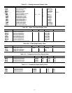
The timings for failure for both are the same and are
illustrated in the following table:
Recovery is manual. Reason for failure may be a broken fan
belt, failed fan relay or failed supply fan status switch.
T414 (Loss of Communication with Belimo Actuator
) — The
Belimo economizer motor is a digital controlled motor. The
ComfortLink™ controls can monitor the status of the motor. If
there is a problem, this alert will occur. The control will attempt
to close the economizer dampers.
T414 (Belimo Actuator Direction Error)
— This alert occurs
when the economizer damper direction switch is in the wrong
position. The direction switch should be in the clockwise posi-
tion and the actuator should be mounted so that the CW face of
the actuator is accessible. Correct if necessary. This alert clears
automatically.
T414 (Belimo Actuator Failure)
— This alert occurs when the
commanded damper position is changing too rapidly. This alert
resets automatically.
T414 (Belimo Actuator Jammed)
— This alert occurs when
the control software has detected that the damper is stuck.
Check the mechanical actuation of the dampers.
T414 (Belimo Actuator Range Error)
— This alert occurs
when the economizer range of motion is less than 90 degrees.
Initiate economizer calibration (Service Test
INDP
E.CAL) using the Service Test menu.
T420 (R-W1 Jumper Must be Installed to Run Heat in Service
Test) — This alert occurs when a request for a heat output has
occurred yet the W1 input is not high. A jumper must be
installed between R and W1 when trying to test heat in Service
Test. The alert will clear when Service Test is exited or if
another Service Test mode is selected. Remove jumper when
done using Service Test if the unit is operating with a thermo-
stat. The jumper should only be left in place if the unit is
operating with a space temperature sensor.
T421 (Thermostat Y2 Input On without Y1 On)
— This alert
occurs in Thermostat Mode when Y2 is energized and Y1 is
not. Verify thermostat and thermostat wiring. When Y2 turns
on, the software will behave as if Y1 and Y2 are both on. When
Y2 turns off, the software will behave as if Y1 and Y2 are both
Off. This alert resets automatically when Y1 is turned on.
T422 (Thermostat W2 Input On without W1 On)
— This alert
occurs in Thermostat Mode when W2 is energized and W1 is
not. Verify thermostat and thermostat wiring. When W2 turns
on, the software will behave as if W1 and W2 are both on.
When W2 turns off, the software will behave as if W1 and W2
are both off. This alert resets automatically when W1 is turned
on.
T423 (Thermostat Y and W Inputs On)
— This alert occurs in
Thermostat Mode when Y1 or Y2 is energized simultaneously
with W1 or W2. Verify thermostat and thermostat wiring. The
software will enter either the cooling or heating mode depend-
ing upon which input turned on first. This alert resets automati-
cally when Y1 and Y2 are not on simultaneously with W1 and
W2.
T424 (Thermostat G Input Off On a Cooling Call)
— This
alert occurs in Thermostat Mode when the fan is not requested
(G = ON) during cooling (Y1 or Y2 = ON). Verify thermostat
and thermostat wiring.
T500 (Current Sensor Board Failure – A1)
T501 (Current Sensor Board Failure – A2)
T502 (Current Sensor Board Failure – B1)
T503 (Current Sensor Board Failure – B2) — Alert codes
500, 501, 502, and 503 are for compressors A1, A2, B1, and
B2 respectively. These alerts occur when the output of the cur-
rent sensor (CS) is a constant high value. These alerts reset au-
tomatically. If the problem cannot be resolved and the CS
board must be replaced, the CS board can be temporarily dis-
abled while securing a replaced board. A CS board is disabled
by setting Configuration
COOL
CS.A1, CS.A2, CS.B1 or
CS.B2 to Disable.
If the current sensor board malfunctions or is not properly
connected to its assigned digital input, an alert will be generat-
ed. It takes 2 to 4 seconds to log the alert. If the alert is logged,
it stays for a minimum of 15 seconds to provide the application
a reasonable time to catch the failure. Compressors will be not
be inhibited by this failure. Recovery is automatic. Reason for
failure may be a faulty current sensor board, incorrect wiring,
or a damaged input on the MBB control board.
A700 (Supply Air Temperature Sensor Failure)
— This alarm
indicates a failure of the sensor supply air temperature sensor
or the leaving air temperature sensor (if using hydronic heat).
This alarm occurs when the temperature sensor (Tempera-
tures
AIR.T
SAT) is outside the range –40 to 240 F (–40 to
116 C). This alarm resets automatically. The cause of the alarm
is usually a faulty thermistor, a shorted or open thermistor
caused by a wiring error, or a loose connection.
T701 (Staged Gas 1 Thermistor Failure)
T702 (Staged Gas 2 Thermistor Failure)
T703 (Staged Gas 3 Thermistor Failure) — If any of the staged
gas thermistors (Temperatures
AIR.T
S.G.L1-3) fails, an
alert will be generated and the remaining thermistors will be
averaged together (Temperatures
AIR.T
S.G.LS) without
the failed thermistor. Recovery is automatic. Reason for failure
may be incorrect wiring, faulty thermistor, or a damaged input
on the staged gas control board (SCB).
A704 (Staged Gas Leaving Air Temperature Sum Total Fail-
ure) — If all three staged gas thermistors (Tempera-
tures
AIR.T
S.G.L1-3) fail (the sensor is outside the range
of –40 F to 240 F), staged gas will be shut down and this alarm
will be generated. Recovery is automatic. Reason for failure
may be faulty wiring, faulty thermistors, or damaged inputs on
the staged gas control board (SCB).
UNIT TYPE/MODE
MINIMUM ON
TIME
MINIMUM OFF
TIME
CV (no gas heat) 30 seconds 1 minute
CV (gas heat) 2 minutes 4 minutes
VAV (IGV/no gas heat) 2 minutes 4 minutes
VAV (VFD/no gas heat) 1 minute 1 minute
VAV (IGV/gas heat) 4 minutes 4 minutes
VAV (VFD/gas heat) 3 minutes 4 minutes