


165
APPENDIX C — VFD INFORMATION (cont)
7. Use the UP or DOWN keys to highlight DATE FOR-
MAT and press SEL (SOFT KEY 2). Use the UP or
DOWN keys to change the parameter setting. Press OK
(SOFT KEY 2) to save the configuration and return to the
Clock Set menu.
8. Press EXIT (SOFT KEY 1) twice to return to the main
menu.
I/O SETTINGS MODE — The I/O Settings mode is used for
viewing and editing the I/O settings.
To configure the I/O settings, perform the following
procedure:
1. Select MENU (SOFT KEY 2). The Main menu will be
displayed.
2. Use the UP or DOWN keys to highlight I/O SETTINGS
on the display screen and press ENTER (SOFT KEY 2).
The I/O Settings parameter list will be displayed.
3. Use the UP or DOWN keys to highlight the desired I/O
setting and press SEL (SOFT KEY 2).
4. Use the UP or DOWN keys to select the parameter to
view. Press OK (SOFT KEY 2).
5. Use the UP or DOWN keys to change the parameter
setting. Press SAVE (SOFT KEY 2) to save the configu-
ration. Press CANCEL (SOFT KEY 1) to keep the previ-
ous value. Any modifications that are not saved will not
be changed.
6. Press EXIT (SOFT KEY 1) twice to return to the main
menu.
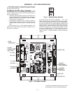
Third Party Controls — For conversion to third party
control of the VFD, perform the following procedure:
1. Remove the factory-installed jumper between X1-10 and
X1-13 (control of VFD start/stop).
2. Remove the factory-installed jumper between X1-10 and
X1-16 and replace with a normally closed safety contact
for control of VFD start enable.
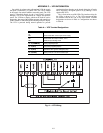
3. Install speed signal wires to AI-1 and AGND. This input
is set at the factory for a 4 to 20 mA signal. If a 0 to
10 vdc signal is required, change DIP switch J1 (located
above the VFD control terminal strip) to OFF (right
position to left position) and change parameter 1301 to
0% from 20%.
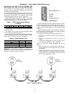
VFD Diagnostics — The drive detects error situations
and reports them using:
• the green and red LEDs on the body of the drive (located
under the keypad)
• the status LED on the control panel
• the control panel display
• the Fault Word and Alarm Word parameter bits (parame-
ters 0305 to 0309)
The form of the display depends on the severity of the error.
The user can specify the severity for many errors by directing
the drive to ignore the error situation, report the situation as an
alarm, or report the situation as a fault.
FAULTS (RED LED LIT) — The VFD signals that it has
detected a severe error, or fault, by:
• enabling the red LED on the drive (LED is either steady
or flashing)
• setting an appropriate bit in a Fault Word parameter
(0305 to 0307)
• overriding the control panel display with the display of a
fault code
• stopping the motor (if it was on)
The fault code on the control panel display is temporary.
Pressing the MENU, ENTER, UP button or DOWN buttons
removes the fault message. The message reappears after a few
seconds if the control panel is not touched and the fault is still
active.
ALARMS (GREEN LED FLASHING) — For less severe
errors, called alarms, the diagnostic display is advisory. For
these situations, the drive is simply reporting that it had detect-
ed something unusual. In these situations, the drive:
• flashes the green LED on the drive (does not apply to
alarms that arise from control panel operation errors)
• sets an appropriate bit in an Alarm Word parameter
(0308 or 0309)
• overrides the control panel display with the display of an
alarm code and/or name
Alarm messages disappear from the control panel display
after a few seconds. The message returns periodically as long
as the alarm condition exists.
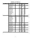
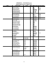
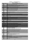
CORRECTING FAULTS — The recommended corrective
action for faults is shown in the Fault Listing Table C. The
VFD can also be reset to remove the fault. If an external source
for a start command is selected and is active, the VFD may
start immediately after fault reset.
To reset a fault indicated by a flashing red LED, turn off the
power for 5 minutes. To reset a fault indicated by a red LED
(not flashing), press RESET from the control panel or turn off
the power for 5 minutes. Depending on the value of parameter
1604 (FAULT RESET SELECT), digital input or serial com-
munication could also be used to reset the drive. When the fault
has been corrected, the motor can be started.
HISTORY — For reference, the last three fault codes are
stored into parameters 0401, 0412, 0413. For the most recent
fault (identified by parameter 0401), the drive stores additional
data (in parameters 0402 through 0411) to aid in troubleshoot-
ing a problem. For example, a parameter 0404 stores the motor
speed at the time of the fault. To clear the fault history (all of
Group 04, Fault History parameters), follow these steps:
1. In the control panel, Parameters mode, select parameter
0401.
2. Press EDIT.
3. Press the UP and DOWN buttons simultaneously.
4. Press SAVE.
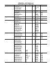
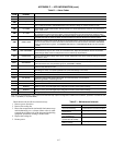
CORRECTING ALARMS — To correct alarms, first deter-
mine if the Alarm requires any corrective action (action is not
always required). Use Table D to find and address the root
cause of the problem.
If diagnostics troubleshooting has determined that the
drive is defective during the warranty period, contact
ABB Automation Inc., at 1-800-435-7365, option 4, option 3.
A qualified technician will review the problem with the caller
and make a determination regarding how to proceed. This may
involve dispatching a designated service station (DSS) repre-
sentative from an authorized station, dispatching a replacement
unit, or advising return for repair.
VFD Maintenance — If installed in an appropriate envi-
ronment, the VFD requires very little maintenance.
Table E lists the routine maintenance intervals recommend-
ed by Carrier.
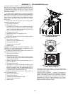
HEAT SINK — The heat sink fins accumulate dust from the
cooling air. Since a dusty sink is less efficient at cooling the
drive, overtemperature faults become more likely. In a normal
environment check the heat sink annually, in a dusty environ-
ment check more often.