


127
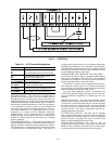
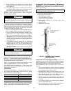
To connect the unit to the network:
1. Turn off power to the control box.
2. Cut the CCN wire and strip the ends of the red (+), white
(ground), and black (–) conductors. (Substitute appropri-
ate colors for different colored cables.)
3. Connect the red wire to (+) terminal on TB3 of the plug,
the white wire to COM terminal, and the black wire to the
(–) terminal.
4. The RJ14 CCN connector on TB3 can also be used, but is
only intended for temporary connection (for example, a
laptop computer running Service Tool).
5. Restore power to unit.
IMPORTANT: A shorted CCN bus cable will prevent
some routines from running and may prevent the unit
from starting. If abnormal conditions occur, unplug the
connector. If conditions return to normal, check the
CCN connector and cable. Run new cable if necessary.
A short in one section of the bus can cause problems
with all system elements on the bus.
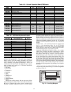
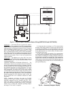
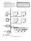
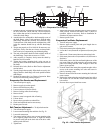
CCN WEB
OR
NETWORK
OPTIONS
REMOTE
CCN SITE
TELINK
NON CARRIER
HVAC
EQUIPMENT
BRIDGE
(RECOM-
MENDED)
CID
ROOFTOP
UNIT
COMFORT
ID AIR
TERMINAL
CID
CID
AIR DISTRIBUTION-DIGITAL AIR VOLUME CONTROL (DAV)
COMFORT ID
FAN
POWERED
MIXING
BOX
TO
ADDITIONAL
TERMINALS
HEATING/COOLING UNITS
COMPUTER WITH
ComfortView™
SOFTWARE
ROOFTOP
UNIT
CL
ROOFTOP
UNIT
CL
ROOFTOP
UNIT
CL
ROOFTOP
UNIT
CL
CCN BUS
CL
COMFORT
CONTROLLER
COMFORT
ID AIR
TERMINAL
LEGEND
CCN — Carrier Comfort Network
®
CID — ComfortID™ Controls
CL — ComfortLink™ Controls
HVAC — Heating, Ventilation, and Air Conditioning
Fig. 35 — CCN System Architecture
COMPUTER WITH
ComfortVIEW™
SOFTWARE
A48-7307