


122
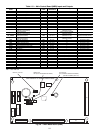
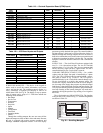
Table 119 — Controls Expansion Board (CEM) Inputs
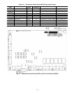
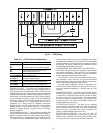
Table 120 — IGC Board Inputs and Outputs
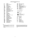
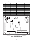
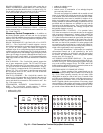
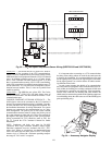
SCROLLING MARQUEE — This device is the keypad in-
terface used to access the control information, read sensor
values, and test the unit. The scrolling marquee display is a
4-key, 4-character, 16-segment LED display as well as an
Alarm Status LED. See Fig. 30. The display is easy to operate
using 4 buttons and a group of 11 LEDs that indicate the
following menu structures:
• Run Status
•Service Test
• Temperatures
•Pressures
• Set points
• Inputs
• Outputs
• Configuration
• Timeclock
• Operating Modes
•Alarms
Through the scrolling marquee the user can access all the
inputs and outputs to check on their values and status. Because
the unit is equipped with suction pressure transducers and
discharge saturation temperature sensors it can also display
pressures typically obtained from gages. The control includes a
full alarm history, which can be accessed from the display. In
addition, through the scrolling marquee the user can access a
built-in test routine that can be used at start-up commission and
to diagnose operational problems with the unit. The scrolling
marquee is located in the main control box and is standard on
all units.
SUPPLY FAN — The size 020 to 050 units are equipped with
two 15 x 11-in. forward-curved fans. The size 051 and 060
units have three 15 x 11-in. fans. They are on a common shaft
and are driven by single belt drive 3-phase motor. The fan is
controlled directly by the ComfortLink™ controls.
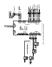
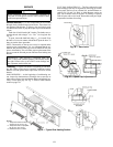
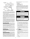
VARIABLE FREQUENCY DRIVE (VFD) — On variable
volume units, the supply fan speed is controlled by a 3-phase
VFD. The VFD is located in the fan section behind a remov-
able panel as shown in Fig. 24 and 25. The VFD speed is
controlled directly by the ComfortLink controls through a 4 to
20 mA signal based on a supply duct pressure sensor. The
inverter has a display, which can be used for service diagnos-
tics, but setup of the supply duct pressure set point and control
loop factors is done through the scrolling marquee display. The
VFD is powered during normal operation to prevent condensa-
tion from forming on the boards during the off mode and is
stopped by driving the speed to 0 (by sending a 2 mA signal to
the VFD).
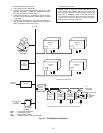
The A Series units use ABB ACH550 VFDs. The interface
wiring for the VFDs is shown in Fig. 31. Terminal designations
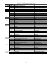
are shown in Table 121.
POINT
NAME
POINT DESCRIPTION
I/O POINT
NAME
PLUG AND PIN
REFERENCE
SIGNAL PIN(S) PORT STATE
INPUTS
SFS Supply Fan Status switch DI 1 J7, 1-2 2 0 = 24vac, 1= 0vac
DMD_SW1 Demand Limit - SW1 DI 2 J7, 3-4 4 0 = 24vac, 1= 0vac
DMD_SW2/
DHD ISCIN
Demand Limit - SW2/
Dehumidification Switch Input
DI 3 J7, 5-6 6 0 = 24vac, 1= 0vac
PRES Pressurization DI 4 J7, 7-8 8 0 = 24vac, 1= 0vac
EVAC Evacuation DI 5 J7, 9-10 10 0 = 24vac, 1= 0vac
PURG Purge DI 6 J7, 11-12 12 0 = 24vac, 1= 0vac
IAQIN Indoor Air Quality Switch DI 7 J7, 13-14 14 0 = 24vac, 1= 0vac
AN7 J6, 1-3 2 (1 = loop power) (0-20mA input)
DMDLMTMA 4-20mA Demand Limit AN8 J6, 4-6 5 (4 = loop power) (0-20mA input)
EDTRESMA 4-20mA Evaporator Discharge SP Reset AN9 J6, 7-9 8 (7 = loop power) (0-20mA input)
OAQ Outside Air CO
2
Sensor AN10 J6, 10-12 11 (10 = loop power) (0-20mA input)
SPRESET SP Reset milliamps AN10 J6, 10-12 11 (10 = loop power) (0-20mA input)
CEM_10K1/
CEM_4201
CEM AN1 10k temp J5,1-2/
CEM AN1 4-20 ma J5,1-2
AN1 J5, 1-2 1 (thermistor, ohms)
CEM_10K2/
CEM_4202
CEM AN2 10k temp J5,3-4/
CEM AN2 4-20 ma J5,3-4
AN2 J5, 3-4 3 (thermistor, ohms)
CEM_10K3/
CEM_4203
CEM AN3 10k temp J5,5-6/
CEM AN3 4-20 ma J5,5-6
AN3 J5, 5-6 5 (thermistor, ohms)
CEM_10K4/
CEM_4204
CEM AN4 10k temp J5,7-8/
CEM AN4 4-20 ma J5,7-8
AN4 J5, 7-8 7 (thermistor, ohms)
AN5 J5, 9-10 9 (thermistor, ohms)
AN6 J5, 11-12 11 (thermistor, ohms)
POINT NAME POINT DESCRIPTION
CONNECTOR
PIN NO.
INPUTS
RT 24 Volt Power Supply R1,C
W Heat Demand 2
GFan 3
LS Limit Switch 7,8
RS Rollout Switch 5,6
SS Hall Effect Sensor 1,2,3
CS Centrifugal Switch (Not Used) 9,10
FS Flame Sense FS
OUTPUTS
CM Induced Draft Motor CM
IFO Indoor Fan IFO
R 24 Volt Power Output (Not Used) R
SPARK Sparker —
LED Display LED
Run Status
Service Test
Temperature
Pressures
Setpoints
Inputs
Outputs
Configuration
Time Clock
Operating Modes
Alarms
Alarm Status
ENTER
MODE
ESCAPE
Fig. 30 — Scrolling Marquee
A30-2239