


42
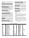
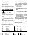
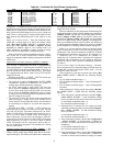
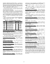
Table 48 — Cool/Heat Set Point Offsets Configuration
Timeguards — In addition to the set points and offsets which
determine the trip points for bringing on and bringing off cool
modes there is a timeguard of 8 minutes which enforces a time
delay between the transitioning from a low cool to a high cool
mode. There is a timeguard of 5 minutes which enforces a time
delay between the transitioning from a heat mode to a cool
mode.
Supply Air Set Point Control — Once the control has deter-
mined that a cooling mode is in effect, the cooling control
point (Run Status
VIEW
CL.C.P) is calculated and is
based upon either Setpoints
SA.HI or Setpoints
SA.LO,
depending on whether a high or a low cooling mode is in
effect, respectively. In addition, if supply air reset is config-
ured, it will also be added to the cooling control point.
Refer to the SumZ Cooling Algorithm section for a discus-
sion of how the A Series ComfortLink™ controls manage
supply-air temperature and the staging of compressors for these
control types.
Thermostat Cool Mode Selection (
C.TYP = 3 and 4) —
When a thermostat type is selected, the decision making pro-
cess involved in determining the mode is straightforward.
Upon energizing the Y1 input only, the unit HVAC mode will
be LOW COOL. Upon the energizing of both Y1 and Y2 in-
puts, the unit HVAC mode will be HIGH COOL. If just input
G is energized the unit HVAC mode will be VENT and the
supply fan will run.
Selecting the C.TYP = 3 (TSTAT – MULTI) control type
will cause the control to do the following:
• The control will read the Configuration
UNIT
SIZE
configuration parameter to determine the number of
cooling stages and the pattern for each stage.
• An HVAC mode equal to LOW COOL will cause the
unit to select the Setpoints
SA.LO set point to control
to. An HVAC mode equal to HIGH COOL will cause the
unit to select the Setpoints
SA.HI set point to control
to. Supply air reset (if configured) will be added to either
the low or high cool set point.
• The control will utilize the SumZ cooling algorithm and
control cooling to a supply air set point. See the section
for the SumZ Cooling Algorithm section for information
on controlling to a supply air set point and compressor
staging.
Selecting the C.TYP = 4 (TSTAT – 2 STG) control type
means that only two stages of cooling will be used. On unit
sizes 020, 025 and 027 (with three compressors), an HVAC
Mode of LOW COOL will energize one compressor in Cir-
cuit A; an HVAC Mode of HIGH COOL will energize all
three compressors. On unit sizes 030 and larger (with four
compressors) an HVAC Mode of LOW COOL will energize
both compressors in Circuit A; an HVAC Mode of HIGH
COOL will energize all four compressors. Refer to the sec-
tion on Economizer Integration with Mechanical Cooling
for more information.
2-Stage Cooling Control Logic (
C.TYP = 4 and 6) — The
logic that stages mechanical cooling for the TSTAT and SPT
2-Stage cooling control types differs from that of the multi-
stage control types. This section will explain how compressors
are staged and the timing involved for both the Low Cool and
High Cool HVAC Modes.
There are either three or four compressors divided among two
refrigeration circuits. Circuit A always contains two compressors
(Outputs
COOL
A1 and A2). Circuit B has either one com-
pressor (Outputs
COOL
B1) on size 020-027 units or two
compressors (Outputs
COOL
B1 and B2) on size 030-060
units. For 2-stage cooling control, regardless of configuration,
there is no minimum load valve (MLV) control. The decision as
to which compressor should be turned on or off next is decided
by the compressor’s availability and the preferred staging order.
Either A1 or A2 may start first as there is a built-in lead/lag
logic on compressors A1 and A2 every time the unit stages to 0
compressors. Also, based on compressor availability, it should
be noted that any compressor may come on. For example, on a
3 compressor unit, if no compressors are currently on,
compressor A2 is currently under a minimum off compressor
timeguard, and 2 compressors are to be turned on, then com-
pressors A1 and B1 will be turned on immediately instead of
A1 and A2.
Low Cool Versus High Cool Mechanical Staging — The num-
ber of compressors to be requested during a cooling mode are
divided into 2 groups by the control, HVAC mode = Lo Cool
and HVAC mode = Hi Cool.
If the economizer is not able to provide free cooling (Run
Status
ECON
ACTV = NO) then the following staging
occurs:
• Lo Cool Mode mechanical stages = 2
• Hi Cool Mode mechanical stages = 3 (for 020 through 027
size units)
• Hi Cool Mode mechanical stages = 4 (for 030 through 060
size units)
If the economizer is able to provide free cooling (Run Sta-
tus
ECON
ACTV = YES) then the following staging
occurs:
1. If the economizer’s current position is less than Configu-
ration
ECON
EC.MX – 5 and mechanical cooling
has not yet started for the current cool mode session then:
Lo Cool Mode mechanical stages = 0
Hi Cool Mode mechanical stages = 0
2. During the first 2.5 minutes of a low or high cool mode
where the economizer position is greater than Configura-
tion
ECON
EC.MX – 5% and mechanical cooling
has not yet started:
Lo Cool Mode mechanical stages = 0
Hi Cool Mode mechanical stages = 0
3. If the economizer position is greater than Configuration
ECON
EC.MX – 5% for more than 2.5 minutes but
less than 5.5 minutes and mechanical cooling has not yet
started then:
Lo Cool Mode mechanical stages = 1
Hi Cool Mode mechanical stages = 1
4. If the economizer position is greater than Configuration
ECON
EC.MX – 5% for more than 5.5 minutes but
less than 8 minutes and mechanical cooling has started
ITEM EXPANSION RANGE UNITS CCN POINT DEFAULT
D.LV.T COOL/HEAT SETPT. OFFSETS
L.H.ON Dmd Level Lo Heat On -1 - 2 ^F DMDLHON 1.5
H.H.ON Dmd Level(+) Hi Heat On 0.5 - 20.0 ^F DMDHHON 0.5
L.H.OF Dmd Level(-) Lo Heat Off 0.5 - 2 ^F DMDLHOFF 1
L.C.ON Dmd Level Lo Cool On -1 - 2 ^F DMDLCON 1.5
H.C.ON Dmd Level(+) Hi Cool On 0.5 - 20.0 ^F DMDHCON 0.5
L.C.OF Dmd Level(-) Lo Cool Off 0.5 - 2 ^F DMDLCOFF 1
C.T.LV Cool Trend Demand Level 0.1 - 5 ^F CTRENDLV 0.1
H.T.LV Heat Trend Demand Level 0.1 - 5 ^F HTRENDLV 0.1
C.T.TM Cool Trend Time 30 - 600 sec CTRENDTM 120
H.T.TM Heat Trend Time 30 - 600 sec HTRENDTM 120