


128
SERVICE
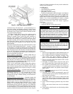
Service Access —
All unit components can be reached
through clearly labelled hinged access doors. These doors are
not equipped with tiebacks, so if heavy duty servicing is need-
ed, either remove them or prop them open to prevent accidental
closure.
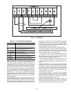
Each door is held closed with 3 latches. The latches are se-
cured to the unit with a single
1
/
4
-in. - 20 x
1
/
2
-in. long bolt. See
Fig. 36.
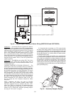
To open, loosen the latch bolt using a
7
/
16
-in. wrench. Pivot
the latch so it is not in contact with the door. Open the door. To
shut, reverse the above procedure.
NOTE: Disassembly of the top cover may be required under
special service circumstances. It is very important that the ori-
entation and position of the top cover be marked on the unit
prior to disassembly. This will allow proper replacement of the
top cover onto the unit and prevent rainwater from leaking into
the unit.
Cleaning — Inspect unit interior at beginning of each heat-
ing and cooling season and as operating conditions require.
Remove unit side panels and/or open doors for access to unit
interior.
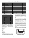
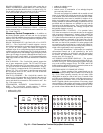
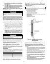
MAIN BURNERS — At the beginning of each heating sea-
son, inspect for deterioration or blockage due to corrosion or
other causes. Observe the main burner flames and adjust if nec-
essary. Check spark gap. See Fig. 37. Refer to Main Burners
section on page 139.
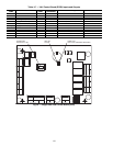
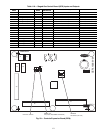
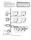
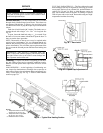
FLUE GAS PASSAGEWAYS — The flue collector box and
heat exchanger cells may be inspected by removing gas section
access panel, flue box cover, collector box, and main burner as-
sembly (Fig. 38 and 39). Refer to Main Burners section on
page 139 for burner removal sequence. If cleaning is required,
clean all parts with a wire brush. Reassemble using new high-
temperature insulation for sealing.
WARNING
Before performing service or maintenance operations on
unit, turn off main power switch to unit. Electrical shock
could cause personal injury.
IMPORTANT: After servicing is completed, make sure
door is closed and relatched properly, and that the latches
are tight. Failure to do so can result in water leakage into
the evaporator section of the unit.
Fig. 36 — Door Latch
Fig. 37 — Spark Gap Adjustment
A48-3821
A48-4022
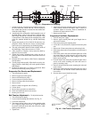
NOTES:
1. Torque set screws on blower
wheel to 70 in. lb ± 2 in. lb.
2. Torque set screw on propeller
fan to 15 in. lb ± 2 in. lb.
3. Dimensions are in inches.
Fig. 38 — Typical Gas Heating Section
A48-3822