


64
Table 80 — Economizer Run Status Table
Building Pressure Config (
BP.CF) — This configuration se-
lects the type of building pressure control.
• BP.CF = 0, No building pressure control
• BP.CF = 1, constant volume two-stage power exhaust
based on economizer position
• BP.CF = 2, multiple stage building pressure control
based on a building pressure sensor
• BP.CF = 3, VFD building pressure control based on a
building pressure sensor
Building Pressure PID Run Rate (
BP.RT) — This configura-
tion selects the run time of the PID algorithm. This configura-
tion is only active when BP.CF = 3. It is recommended that this
value not be changed without guidance from Service
Engineering.
Building Pressure Proportional Gain (
BP.P) — This configura-
tion selects the proportional gain of the PID algorithm. This
configuration is only active when BP.CF = 3. It is recommend-
ed that this value not be changed without guidance from Service
Engineering.
Building Pressure Integral Gain (
BP.I) — This configuration
selects the integral gain of the PID algorithm. This configuration
is only active when BP.CF = 3. It is recommended that this val-
ue not be changed without guidance from Service Engineering.
Building Pressure Derivative Gain (
BP.D) — This configura-
tion selects the derivative gain of the PID algorithm. This con-
figuration is only active when BP.CF = 3. It is recommended
that this value not be changed without guidance from Service
Engineering.
Building Pressure Set Point Offset (
BP.SO) — This configura-
tion is the value below the building pressure set point to which
the building pressure must fall in order to turn off power exhaust
control. This configuration is only active when BP.CF = 3.
Building Pressure Minimum Speed (
BP.MN) — This configu-
ration is the minimum allowed VFD speed during building pres-
sure control. This configuration is only active when BP.CF = 3.
Building Pressure Maximum Speed (
BP.MX) — This configu-
ration is the maximum allowed VFD speed during building
pressure control. This configuration is only active when BP.CF
= 3.
VFD Fire Speed (
BP.FS) — This configuration is the VFD
speed override when the control is in the purge or evacuation
smoke control modes. This configuration is only active when
BP.CF = 3.
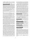
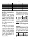
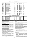
Power Exhaust Motors (
BP.MT) — This configuration is ma-
chine dependent and instructs the building pressure control
algorithm as to whether the unit has 4 or 6 motors to control.
The motors are controlled by three power exhaust relays A, B,
and C. These relay outputs are located at the local display un-
der Outputs
FANS
PE.A,B,C.
The following table illustrates the number of motors each
relay is in control of based on BP.MT:
Building Pressure Sensor (
BP.S) — This configuration al-
lows the reading of a building pressure sensor when enabled.
This is automatically enabled when BP.CF = 2 or 3.
Building Pressure (+/–) Range (
BP.R) — This configuration
establishes the range in in. wg that a 4 to 20 mA sensor will be
scaled to. The control only allows sensors that measure both
positive and negative pressure.
Building Pressure SETP (
BP.SP) — This set point is the
building pressure control set point. If the unit is configured for
modulating building pressure control, then this is the set point
that the control will control to.
Power Exhaust on Setp.1 (
BP.P1) — When configured for
building pressure control type BP.CF = 1 (constant volume two-
stage control), the control will turn on the first power exhaust
fan when the economizer’s position exceeds this set point.
Power Exhaust on Setp.1 (
BP.P2) — When configured for
building pressure control type BP.CF = 1 (constant volume two-
stage control), the control will turn on the second power exhaust
fan when the economizer’s position exceeds this set point.
Modulating PE Algorithm Select (
BP.SL) — This configuration
selects the algorithm used to step the power exhaust stages. This
must be set to 1 at all times. The other selections are not used.
Building Pressure PID Evaluation Time (
BP.TM) — This
configuration is the run time rate of the multiple stage (modu-
lating) power exhaust algorithm (BP.CF=2).
Building Pressure Threshold Adjustment (
BP.ZG) — This
configuration is not used. It currently has no effect on building
pressure control.
High Building Pressure Level (
BP.HP) — This configura-
tion is the threshold level above the building pressure set point
used to control stages of power exhaust when BP.SL=1.
Low Building Pressure Level (
BP.LP) — This configuration
is the threshold level below the building pressure set point used
to control stages of power exhaust when BP.SL=1.
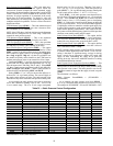
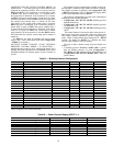
ITEM EXPANSION RANGE UNITS CCN POINT
WRITE STATUS
ECN.P Economizer Act.Curr.Pos. 0-100 % ECONOPOS
ECN.C Economizer Act.Cmd.Pos. 0-100 % ECONOCMD forcible
ACTV Economizer Active ? YES/NO ECACTIVE
DISA
ECON DISABLING CONDITIONS
UNAV Econ Act. Unavailable? YES/NO ECONUNAV
R.EC.D Remote Econ. Disabled? YES/NO ECONDISA
DBC DBC - OAT Lockout? YES/NO DBC_STAT
DEW DEW - OA Dewpt.Lockout? YES/NO DEW_STAT
DDBC DDBD- OAT > RAT Lockout? YES/NO DDBCSTAT
OAEC OAEC- OA Enth Lockout? YES/NO OAECSTAT
DEC DEC - Diff.Enth.Lockout? YES/NO DEC_STAT
EDT EDT Sensor Bad? YES/NO EDT_STAT
OAT OAT Sensor Bad ? YES/NO OAT_STAT
FORC Economizer Forced ? YES/NO ECONFORC
SFON Supply Fan Not On 30s ? YES/NO SFONSTAT
CLOF Cool Mode Not In Effect? YES/NO COOL_OFF
OAQL OAQ Lockout in Effect ? YES/NO OAQLOCKD
HELD Econ Recovery Hold Off? YES/NO ECONHELD
DH.DS Dehumid. Disabled Econ.? YES/NO DHDISABL
O.AIR OUTSIDE AIR INFORMATION
OAT Outside Air Temperature dF OAT forcible
OA.RH Outside Air Rel. Humidity % OARH forcible
OA.E Outside Air Enthalpy OAE
OA.D.T Outside Air Dewpoint Temp dF OADEWTMP
BP.MT PE_A Relay PE_B Relay PE_C Relay
1 (4 motors) 1 Motor 2 Motors 1 Motor
2 (6 motors) 1 Motor 2 Motors 3 Motors