


126
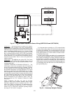
Green LED
— The boards also have a green LED, which is
the indicator of the operation of the LEN communications,
which is used for communications between the boards. On the
MBB board the Local Equipment Network (LEN) LED should
always be blinking whenever power is on. All other boards
have a LEN LED that will blink whenever power is on and
there is communication occurring. If LEN LED is not blinking,
check LEN connections for potential communication errors (J3
and J4 connectors). A 3-wire sensor bus accomplishes commu-
nication between modules. These 3 wires run in parallel from
module to module.
Yellow LED
— The MBB has one yellow LED. The Carrier
Comfort Network
®
(CCN) LED will blink during times of
network communication. The other boards do not have a CCN
communications port.
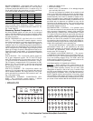
CARRIER COMFORT NETWORK INTERFACE — The
48/50A Series units can be connected to the CCN interface if
desired. The communication bus wiring is a shielded, 3-conduc-
tor cable with drain wire and is field supplied and installed. See
the Installation Instructions for wiring information. The system
elements are connected to the communication bus in a daisy
chain arrangement. The positive pin of each system element
communication connector must be wired to the positive pins of
the system elements on either side of it. This is also required for
the negative and signal ground pins of each system element.
Wiring connections for CCN should be made at TB3. See
Fig. 35. Consult the CCN Contractor’s Manual for further
information.
NOTE: Conductors and drain wire must be 20-AWG
(American Wire Gage) minimum stranded, tinned copper.
Individual conductors must be insulated with PVC, PVC/
nylon, vinyl, Teflon, or polyethylene. An aluminum/polyester
100% foil shield and an outer jacket of PVC, PVC/nylon,
chrome vinyl, or Teflon with a minimum operating tempera-
ture range of –20 C to 60 C is required.
It is important when connecting to a CCN communication
bus that a color-coding scheme be used for the entire network
to simplify the installation. It is recommended that red be used
for the signal positive, black for the signal negative and white
for the signal ground. Use a similar scheme for cables contain-
ing different colored wires.
At each system element, the shields of its communication
bus cables must be tied together. If the communication bus is en-
tirely within one building, the resulting continuous shield must
be connected to a ground at one point only. If the communica-
tion bus cable exits from one building and enters another, the
shields must be connected to grounds at the lightning suppressor
in each building where the cable enters or exits the building (one
point per building only).
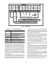
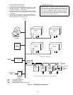
J6
TB4
1
2
3
4
5
6
7
1
2
3
4
5
6
7
TB5
UNIT CONTROL BOX
1
2
J3
J5
J4
B4
OVERRIDE
3
2
1
1
2
3
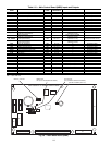
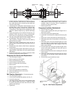
Fig. 33 — CO
2
and Space Temperature Sensor Wiring (33ZCT55CO2 and 33ZCT56CO2)
A48-7306
Ru
n Sta
tu
s
S
e
rv
ice
Te
s
t
T
em
p
era
ture
s
P
res
s
ure
s
S
e
tpo
in
ts
In
pu
ts
O
utp
uts
C
on
fig
u
ra
tion
T
im
e
Clo
ck
O
p
er
ating
M
od
es
A
la
rm
s
E
N
T
E
R
E
S
C
M
O
D
E
Ala
rm
Sta
tus
T
IM
E
E
W
T
L
W
T
S
E
T
P
1
2
.
5
8
5
4
.
6
F
4
4
.1
F
4
4
.
0
F
N
A
V
I
G
A
T
O
R
C
o
m
f
o
r
t
L
in
k
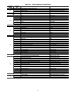
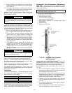
Fig. 34 — Accessory Navigator Display