


123
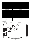
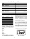
Table 121 — VFD Terminal Designations
POWER EXHAUST — The units can be equipped with an
optional power exhaust system. The power exhaust fans are
forward-curved fans with direct-drive motors. The motors are
controlled directly by the ComfortLink™ controls through the
ECB1 board. On the 48/50A020-050 units there are 4 fans. On
the 48/50A051 and 060 units there are 6 fans. The fan sequenc-
es are controlled to provide 4 stages on the 48/50A020-050
units and 6 stages on the 48/50A051 and 060 units. There are
two control methods. For CV applications the fans can be
configured for 2 stages based on adjustable economizer
damper positions. For VAV applications and CV units with the
building pressure control option, the fans are sequenced to
maintain a building pressure set point based on a building
pressure transducer.
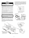
ECONOMIZER MOTOR — The economizer outside air and
return air dampers are gear-driven dampers without linkage. A
digitally controlled economizer motor controls their position.
The motor position is controlled by the ECB1 board by means
of a digital two-way communication signal. This allows for
accurate control of the motors as well as feedback information
and diagnostics information. The control has a self-calibration
routine that allows the motor position to be configured at initial
unit start-up. The motor is located on the economizer and can
be reached through the filter access door.
THERMISTORS AND PRESSURE TRANSDUCERS —
The 48/50AJ,AK,AW,AY units are equipped with thermistors
and pressure transducers. These units have two thermistors
connected to the condenser coil and two pressure transducers
that are connected to the low side of the system.
The 48/50A2,A3,A4,A5 units are equipped with four pres-
sure transducers. These units have two pressure transducers
connected to the low side of the system and two pressure trans-
ducers connected to the high side of the system.
By using either temperature sensors or transducers, the
ComfortLink controller displays the high and low side pres-
sures and saturation temperatures. A normal gage set is not
required.
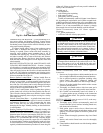
SMOKE DETECTOR — The units can be equipped with an
optional smoke detector located in the return air. The detector
is wired to the ComfortLink controls and, if activated, will stop
the unit by means of a special fire mode. The smoke detector
can also be wired to an external alarm system through TB5
terminals 10 and 11. The sensor is located in the return air sec-
tion behind the filter access door.
FILTER STATUS SWITCH — The units can be equipped
with an optional filter status switch. The switch measures the
pressure drop across the filters and closes when an adjustable
pressure set point is exceeded. The sensor is located in the
return air section behind the filter access door.
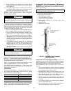
RETURN AIR CO
2
SENSOR — The unit can also be
equipped with a return air IAQ CO
2
sensor that is used for the
demand control ventilation. The sensor is located in the return
air section and can be accessed from the filter access door.
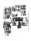
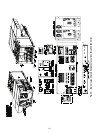
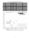
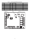
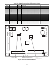
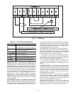
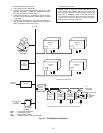
Fig. 31 — VFD Wiring
+
–
A48-7709
TERMINAL FUNCTION
U1
V1
W1 Three-Phase Main Circuit Input Power Supply
U2
V2 Three-Phase AC Output to Motor, 0 V to
W2 Maximum Input Voltage Level
X1-11 (GND)
X1-12 (COMMON) Factory-supplied jumper
X1-10 (24 VDC)
X1-13 (DI-1) Run (factory-supplied jumper)
X1-10 (24 VDC) Start Enable 1 (factory-supplied jumper). When
X1-16 (DI-4) opened the drive goes to emergency stop.
X1-2 (AI-1)
X1-3 (AGND) Factory wired for 4 to 20 mA remote input