


2 - 80
2 SYSTEM CONFIGURATION
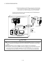
!
CAUTION
Do not connect the A31TU-D3 to the cable for teaching unit (Q170TUDNCBL03M-A). The protective
function stops working.
Be sure to fix the relay portion of a connector which has connected the cable for teaching unit
(Q170TUDNCBL03M-A) with teaching unit (A31TU-DN
) so that impossible power is not applied
for the connector of Motion CPU (Q173CPUN-T/Q172CPUN-T). A connector may be damaged.
Do not pull a teaching unit (A31TU-DN ). A connector may be damaged.
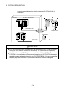
When a teaching unit (A31TU-DN ) is removed, first be sure to remove a TU connector of Motion
CPU (Q173CPUN-T/Q172CPUN-T) so that impossible power is not applied for the connector.
If a connector of teaching unit (A31TU-DN
) is removed connecting a TU connector of Motion
CPU (Q173CPUN-T/Q172CPUN-T), a TU connector of Motion CPU (Q173CPUN-T/
Q172CPUN-T) may be damaged.
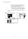
When the teaching unit (A31TU-DN ) is not used in the Motion CPU (Q173CPUN-T/
Q172CPUN-T), connect the short-circuit connector for teaching unit (Q170TUTM) after removing
a TU connector of cable for teaching unit (Q170TUDNCBL03M-A) from a TU connector of Motion
CPU (Q173CPUN-T/Q172CPUN-T). If it is not connected, the emergency stop state of Motion
CPU occurs, and the servomotor becomes coasting state.