3 - 20
3 DESIGN
3.4 Design Checklist
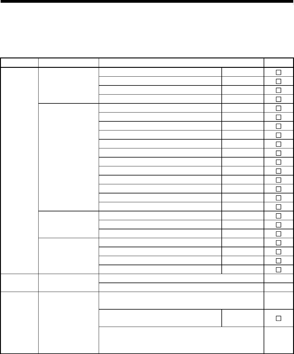
At the worksite, copy the following table for use as a check sheet.
Item Sub Item Design confirmation Check
Number of axes axes
Number of I/O points points
Motion CPU module selection
CPU module selection
PLC CPU module selection
Manual pulse generator pcs.
Synchronous encoder pcs.
Teaching unit
Upper limit point points
Lower limit point points
STOP input point points
Proximity dog input point points
Speed switching input point points
Tracking enable signal point points
Q172LX modules
Q172EX modules
Motion module
selection
Q173PX modules
Motion CPU module modules
I/O module installed to CPU base modules
CPU base unit
selection
CPU base unit selection
I/O module installed to extension base modules
Distance between CPU base and extension base mm
Extension base unit selection
Module
selection
Extension base unit
and extension cable
selection
Extension cable selection
Avoidance of operation failure at power-on
External
circuit design
Fail-safe circuit design
Avoidance of hazard at Motion controller failure
Conformance with general specifications such as ambient
temperature, humidity, dust, etc.
Total power consumption of base unit
(Calculate the heating value)
W
Layout
design
Module layout design
Layout in consideration of clearances between enclosure's inside
walls, other structures and modules and heats generated by
modules within the control panel.


