2 - 91
2 SYSTEM CONFIGURATION
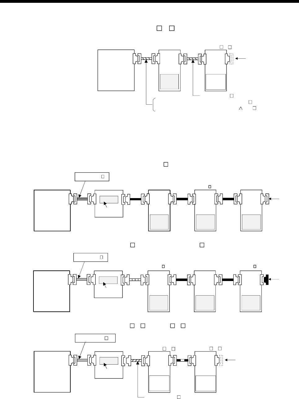
(h) MR-H-BN + FR-V5 0- configuration
Q172CPU(N) configuration : Q172HBCBL M
Q173CPU(N) configuration : Q173HB CBL M
Motion CPU
module
Q173CPU(N)
/Q172CPU(N)
Terminal connector
setting is set by
connector in FR-V5NS.
MR-H-BN
SSCNET
communication
option
FR-V5NS
FR-V5 0-
Battery
MR-BAT,
A6BAT
Q172HBCBL M
(i) When using the external battery
As the SSCNET cable used depend on the servo amplifiers, when using
the external battery, refer to the following connection example.
1) Example of Q173CPU(N)
• MR-H-BN + MR-J2 -B + MR-H-BN configuration
Battery
Q173DV
Motion
CPU module
MR-BAT,
A6BAT
Terminal
connector
Q173CPU(N)
Battery
MR-BAT,
A6BAT
Battery
MR-BAT,
A6BAT
Battery
MR-BAT,
A6BAT
Q173DVCBL M
MR-H-BN MR-H-BNMR-J2 -B
• MR-J2
-B + MR-H-BN + MR-J2 -B configuration
Battery
Q173DV
Motion
CPU module
MR-BAT,
A6BAT
Terminal
connector
Q173CPU(N)
Battery
MR-BAT,
A6BAT
Battery
MR-BAT,
A6BAT
Battery
MR-BAT,
A6BAT
Q173DVCBL M
MR-H-BNMR-J2 -B MR-J2 -B
• FR-V5
0- + FR-V5 0- configuration
Motion CPU
module
Q173CPU(N)
Battery
Q173DV
MR-BAT,
A6BAT
Q173DVCBL M
Terminal connector
setting is set by
connector in FR-V5NS.
SSCNET
communication
option
FR-V5NS
FR-V5 0-
SSCNET
communication
option
FR-V5NS
FR-V5 0-
Q172J2BCBL M


