


2 - 68
2 SYSTEM CONFIGURATION
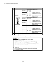
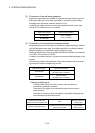
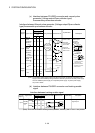
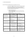
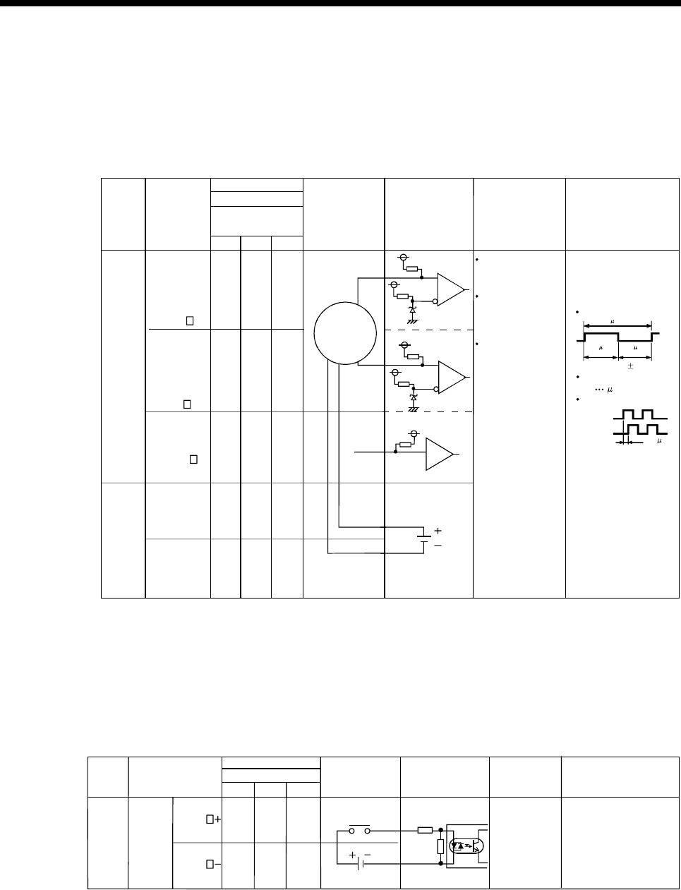
(c) Interface between PULSER connector and manual pulse
generator (Voltage output/Open collector type)/
Incremental synchronous encoder.
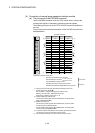
Interface between Manual pulse generator (Voltage-output/Open collector
type)/Incremental synchronous encoder
A
Manual pulse
generator/
synchronous
encoder
Input or
Output
Signal name
Pin No.
PULSER connector
Wiring example Internal circuit
Specification
Description
5V
Input
A20
Voltage-Output
type
A15 A10
Manual
pulse
generator,
phase A
B20 B15 B10
A18 A13 A8
Power
supply
P5
SG
B18 B13 B8
A19 A14 A9
B19 B14 B9
SG
No connect
Rated input voltage
5.5VDC or less
HIGH level
3 to 5.25VDC/
2mA or less
1VDC or less/
5mA or more
For connection
manual pulse
generator
Phases A, B
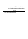
Pulse width
(1) Positioning address
increases if Phase A
leads Phase B.
Phase difference
B
Power supply
5VDC
123
Manual
pulse
generator,
phase B
HA
HB
LOW level
Rise, fall time
1 s or less
(2) Positioning address
decreases if Phase B
leads Phase A.
Select type
signal
HPSEL
The 5V(P5)DC power supply from the Q173PX must not be connected if a separated power
supply is used as the Manual pulse generator/Incremental synchronous encoder power supply.
Use a 5V stabilized power supply as a separated power supply. Any other power supply
may cause a failure.
(Note) :
(Note)
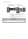
Phase A
2.5 s or
Phase B
more
(Duty ratio: 50% 25%)
20 s or more
5 s
or more
5 s
or more
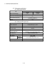
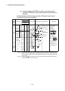
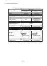
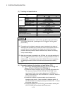
(d) Interface between PULSER connector and tracking enable
signal
Interface between tracking enable signal
Signal name
PULSER connector
Wiring example Internal circuit Specification Description
12V to 24VDC
Input or
Output
Tracking
enable
(Note)
A4 A3 A2
B4 B3 B2
1 2 3
Tracking enable
signal input.
Input
TREN
TREN
Pin No.
(Note) : As for the connection to tracking enable (TREN+, TREN–), both "+" and "–" are possible.