


4 - 18
4 INSTALLATION AND WIRING
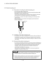
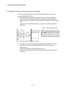
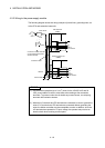
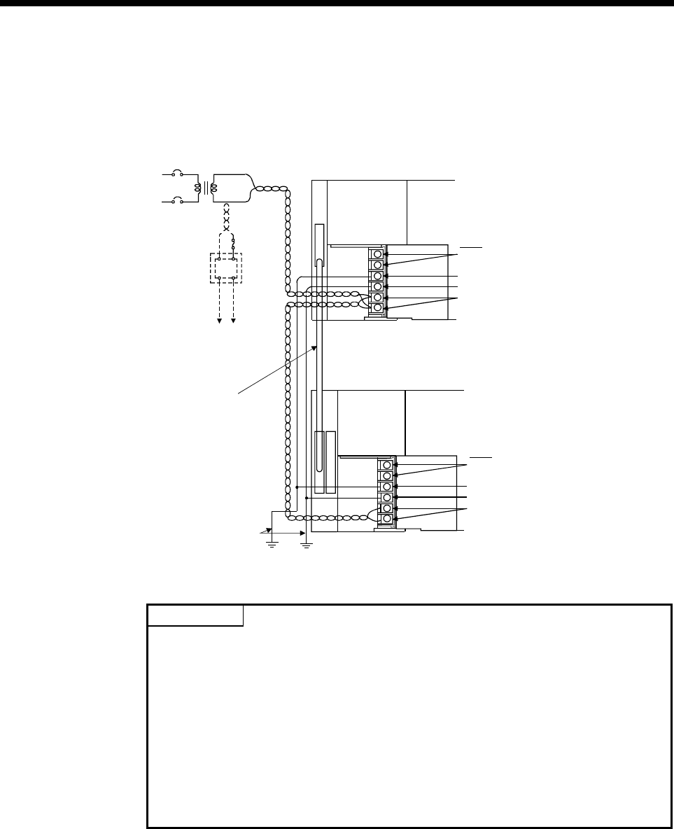
4.5.2 Wiring to the power supply module
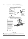
The following diagram shows the wiring example of power lines, grounding lines, etc.
to the CPU and extension base units.
AC
100/110VAC
Fuse
24VDC
AC
DC
Connect to 24VDC terminals
of I/O module that requires
24VDC internally.
Extension cable
Ground wire
Grounding
CPU base unit
(Q38B)
Q61P-A1 CPU
Extension base unit
(Q68B)
Q61P-A1 I/O
100VAC
ERR
FG
LG
INPUT
100-120VAC
FG
LG
INPUT
100-120VAC
ERR
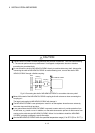
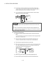
POINT
(1) Use the thickest possible (up to 2 mm
2
) wires for the 100/200 VAC and 24
VDC power cables. Be sure to twist these wires starting at the connection
terminals. To prevent a short circuit should any screws loosen, use crimping
terminals with insulation sleeves.
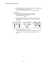
(2) When the LG terminals and FG terminals are connected, be sure to ground the
wires. If LG terminals and FG terminals are connected without grounding the
wires, the Motion controller may be susceptible to noise. In addition, since the
LG terminals have potential of ½ input voltage, the operator may receive an
electric shock when touching terminal parts.