4 - 16
4 INSTALLATION AND WIRING
(b) Do not bunch or lay them closely the main circuit (high voltage, large
current) cables of the 100VAC and 24VDC with the I/O signal cables. If
possible, separate them 100mm (3.94inch) or more away.
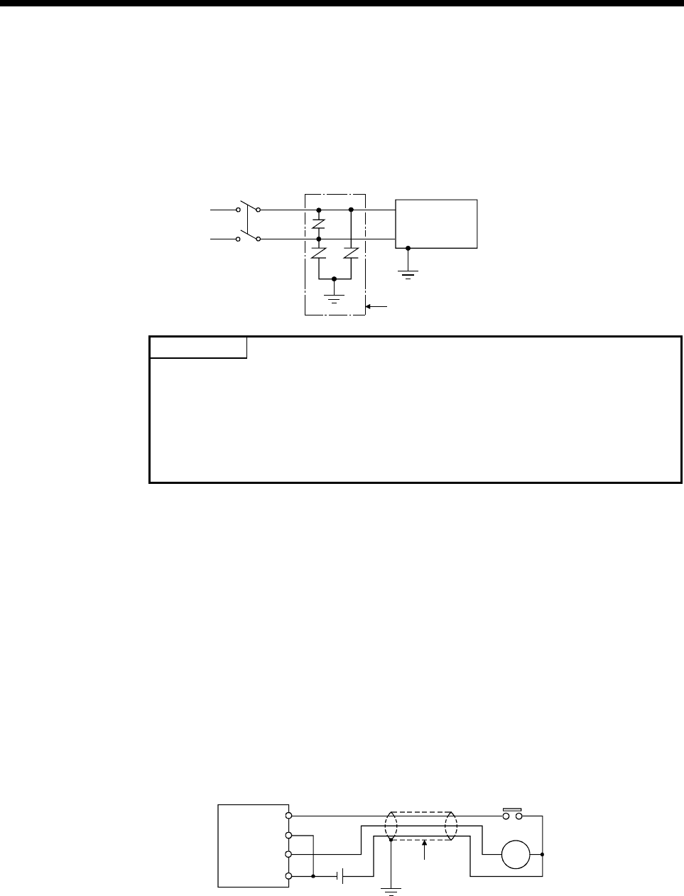
(c) As a countermeasure to power surge due to thunder, connect a surge
absorber for thunder as shown below.
AC
E1
E2
Surge absorber for thunde
r
Multiple CPU
system
POINTS
(1) Separate the ground of the surge absorber for thunder (E1) from that of the
PLC (E2).
(2) Select a surge absorber for thunder whose power supply voltage does not
exceed the maximum allowable circuit voltage even if at the time of maximum
power supply voltage elevation.
(2) Wiring of I/O equipment
(a) Insulation-sleeved crimping terminals cannot be used with the terminal
block.
It is recommended to cover the wire connections of the crimping terminals
with mark or insulation tubes.
(b) The wires used for connection to the terminal block should be 0.3 to
0.75mm
2
in core and 2.8mm (0.11inch) or less in outside diameter.
(c) Run the input and output lines away from each other.
(d) When the wiring cannot be run away from the main circuit and power lines,
use a batch-shielded cable and ground it on the Motion controller side.
In some cases, ground it in the opposite side.
Input
Output
Multiple CPU system
Shielded cable
Shield
DC
RA
(e) Where wiring runs through piping, ground the piping without fail.
(f) Run the 24VDC input line away from the 100VAC and 200VAC lines.


