


5 - 3
5 TRIAL OPERATION AND ADJUSTMENT
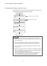
2)
Motion CPU
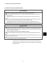
CAUTION
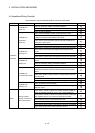
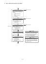
[Servo data setting
mode]
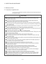
CAUTION
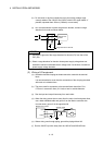
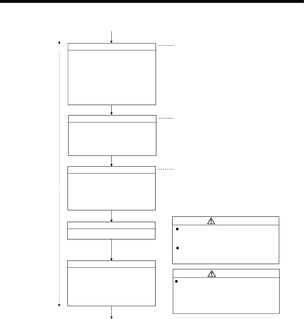
Check external inputs to Q172LX
Check the wiring of following external
inputs by monitoring of the peripheral
device.
(1) FLS
(Upper stroke limit input)
(2) RLS
(Lower stroke limit input)
(3) STOP
(Stop signal)
I/O module
Check the I/O module wiring.
Refer to Section 2.4.4
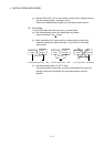
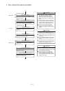
Check external inputs to Q172EX
Check the wiring of following external
inputs by monitoring of the peripheral
device or LED indicators.
(1) Serial absolute synchronous
encoder setting
Refer to Section 2.4.5
Refer to Section 2.4.6
Check external inputs to Q173PX
Check the wiring of following external
inputs by monitoring of the peripheral
device or LED indicators.
(1) Manual pulse generator/
incremental synchronous
encoder setting
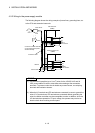
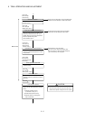
Positioning parameters setting
Set the following positioning parameters
by the peripheral device.
(1) Fixed parameters
(2) Servo parameters
(3) Home position return data
(4) Limit switch
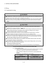
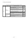
Do not install a phase advancing capacitor,
surge absorber or radio noise filter (option FR-
BIF) on the output side of the servo amplifier.
Correctly connect the output side (terminal U, V,
W). Incorrect connections will lead the
servomotor to operate abnormally.
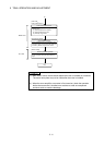
Set parameter values to those that are
compatible with the Motion controller, servo
amplifier, servomotor and regenerative resistor
model name and the system name application.
The protective functions may not function if the
settings are incorrect.
1)