2 - 74
2 SYSTEM CONFIGURATION
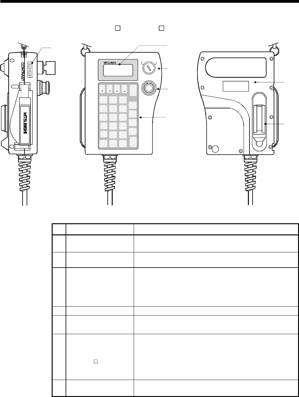
(2) A31TU-D3 /A31TU-DN Name of parts
DISABLE
EMG.STOP
ENABLE
5)
1)
2)
3)
4)
6)
7)
A31TU
DATA
MONITOR
TEST
STOP
OVERRIDE
STEP -
STEP +
RETURN
8
ITEM
#
9
CLEAR
5
DELETE
E
6
INDIRECT
F
3
C
2
B
0
MDI
-
7
INSTRUCTION
;
4
WRITE
D
1
STORE
A
.
SHIFT
AXIS
NO.
FUNCTION
PROGR AM
JOG -
ERROR
RESET
SP
CAN
JOG +
GO
No. Name Application
1) Display
4 lines × 16 characters LCD display
(With back-lighted auto light off)
2)
DISABLE/ENABLE key
select switch
Switch the operation of teaching unit to DISABLE/ENABLE
3)
Emergency stop switch
EMG.STOP button
Input the emergency stop signal to the Motion CPU.
The emergency stop state of Motion CPU occurs by pushing the switch,
and the servomotor stops and becomes coasting state.
The emergency stop state is released by turning to the right this switch.
4) Operation keys
Operation key of the teaching unit
5) Contrast adjusting switch
Adjust the contrast of display.
6)
3-position deadman switch
(A31TU-D3
only)
The emergency stop signal is input to the Motion CPU by the external
safety circuit.
The Motion CPU will be in the state which can be operated by holding the
middle position of enable switch.
The emergency stop state of Motion CPU occurs by gripping or releasing
this switch, and the servomotor stops and becomes coasting state.
7) Internal buzzer
Buzzer sounds at the operation key input or any alarm occurrence.
(It is possible to switch off the buzzer at the key input by setting.)


