


2 - 77
2 SYSTEM CONFIGURATION
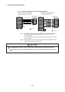
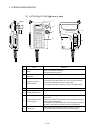
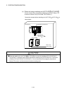
(b) Connection between the teaching unit (A31TU-DN ) and
Motion CPU (Q173CPUN-T/Q172CPUN-T)
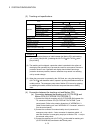
There are following two connecting method.
• When the connector is connected to the control panel.
• When the connector is connected directly in the control panel.
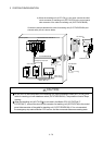
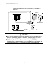
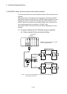
1) When the connector is connected to the control panel.
a) Connect the cable for teaching unit (Q170TUDNCBL3M) between
the TU connector of Motion CPU (Q173CPUN-T/Q172CPUN-T) and
control panel. (Refer to the exterior dimensions of "APPENDIX 1.3
Cable for the teaching unit" and "APPENDIX 2.7 Connector", when
it is fit to the control panel.)
b) Connect the teaching unit (A31TU-DN
) to the cable for teaching
unit (Q170TUDNCBL3M) connected to the control panel.
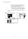
c) When the teaching unit (A31TU-DN
) is not used, connect the
short-circuit connector for teaching unit (A31TUD3TM) to the control
panel side connector of the cable for teaching unit
(Q170TUDNCBL3M).