


4 - 14
4 INSTALLATION AND WIRING
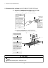
4.4 Replacement of the Cooling fan unit (Q170FAN) (Q173CPU/Q172CPU only)
(1) Removal and installation of the cooling fan unit (Q170FAN)
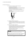
(a) Removal of cooling fan unit from Q173CPU/Q172CPU
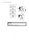
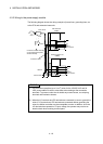
The removal of the cooling fan unit are described below.
Completion
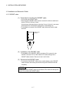
Remove the cooling fan con-
nector from the Motion CPU
connector.
Q173CPU/
Q172CPU
module
Cooling fan unit
The screwdriver
insert this point,
lift upwards and
removed the
cooling fan unit.
Insert the screwdriver be-
tween the cooling fan unit
and the Motion CPU module
holding the cooling fan unit,
lift the cooling fan unit
upwards and remove the
front side fixing hook of the
cooling fan unit from the slit
of the Motion CPU.
(Q170FAN)
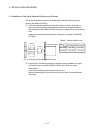
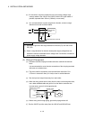
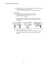
(b) Installation of cooling fan unit on Q173CPU/Q172CPU
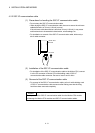
The installation of the cooling fan unit are described below.
Completion
Connect the cooling fan unit
connector to the connector
in the top of the Motion CPU.
While rear side hook of the
cooling fan unit pushing from
the top, and insert another
hook into the slit of the
Motion CPU.
Insert the front side fixing
hook to the slit of the cooling
fan unit connector in the top
of the Motion CPU.
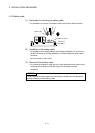
Make sure that the connector
correctly connected in the
connector of the Motion CPU.
Q173CPU
Connecto
r
Cooling fan unit (Q170FAN)
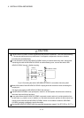
!
CAUTION
Forcibly installation or removal the cooling fan unit will damage the cover or printed circuit board of
modules.
When install the cooling fan unit, do not pinch the wire.