


2 - 76
2 SYSTEM CONFIGURATION
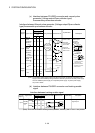
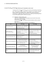
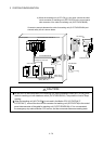
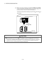
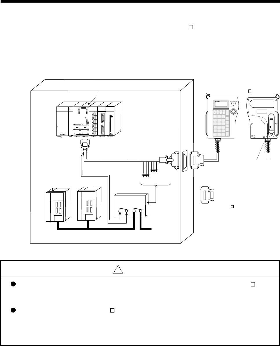
4) When the teaching unit (A31TU-D3
) is not used, connect the short-
circuit connector for teaching unit (A31TUD3TM) to the control panel
side connector of the cable for teaching unit (Q170TUD3CBL3M).
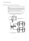
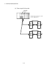
Connection example between the cable for teaching unit (Q170TUD3CBL3M) and
external safety circuit is shown below.
MITSUBISHI
Q173C PUN-T
SSCNET
M.RUN
MODE
RUN
ERR.
BAT.
BOOT
FRONT
CN2
CN1
PULL
USB
RS-232
TU
QX40
0 1 2 3 4 5 6 7
8 9 A B C D E F
SY.EN C2
SY.EN C1
Q172EX
Q172EX
2
1
TREN
SY.ENC
2
1
Q02HCPU
USER
MOD E
RUN
ERR.
BAT.
BOOT
PUL L
USB
RS-232
Q61P-A1
POWER
PULL
Q173PX
PULSER
Q173PX-S1
PLS.A
3
2
1
PLS.B
3
2
1
TREN
3
2
1
MELSEC
MITSUBISHI
DISA BLE
EMG.STOP
ENABLE
Q170TUD3CBL3M
Q173CPUN-T/Q172CPUN-T
Control panel
A31TUD3TM
When the A31TU-D3
is not used.
Emergency stop input
Deadman
contact point
Emergency stop
contact point
Main circuit
power supply
External safety circuit
(Relay, MC, etc.)
A31TU-D3
Deadman switch
A31TU
DATA
MONITOR
TEST
STOP
OVERRIDE
STEP -
STEP +
RETURN
8
ITEM
#
9
CLEAR
5
DELETE
E
6
INDIRECT
F
3
C
2
B
0
MDI
-
7
INSTRUCTION
;
4
WRITE
D
1
STORE
A
.
SHIFT
AXIS
NO.
FUNCTION
PROGRAM
JOG -
ERROR
RESET
SP
CAN
JOG +
GO
Servo amplifier
!
CAUTION
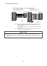
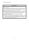
Do not use it in the combination of the teaching unit without deadman switch (A31TU-DN ) and
cable for teaching unit with deadman switch (Q170TUD3CBL3M). The protective function stops
working.
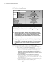
When the teaching unit (A31TU-D3 ) is not used in the Motion CPU (Q173CPUN-T/
Q172CPUN-T), connect the short-circuit connector for teaching unit (A31TUD3TM) to the control
panel side connector of the cable for teaching unit (Q170TUD3CBL3M). If it is not connected,
the emergency stop state of Motion CPU occurs, and the servomotor becomes coasting state.