2 - 81
2 SYSTEM CONFIGURATION
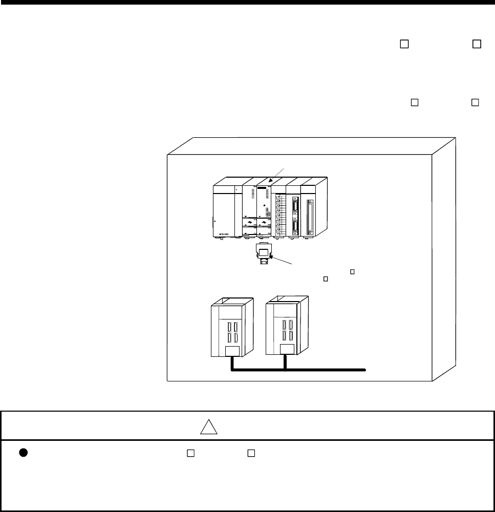
(c) When not using a teaching unit (A31TU-D3 /A31TU-DN )
Connect a short-circuit connector for teaching unit (Q170TUTM) to a TU
connector of Motion CPU (Q173CPUN-T/Q172CPUN-T).
Connection example without teaching unit (A31TU-D3
/A31TU-DN ) is
shown below.
MITSUBISHI
Q173C PUN-T
SSCNET
M.R UN
MODE
RUN
ERR.
BAT.
BOOT
FRONT
CN2
CN1
PULL
USB
RS-232
TU
QX40
0 1 2 3 4 5 6 7
8 9 A B C D E F
SY.EN C2
SY.EN C1
Q172EX
Q172EX
2
1
TREN
SY.ENC
2
1
Q02HCPU
USER
MODE
RUN
ERR.
BAT.
BOOT
PUL L
USB
RS-232
Q61P-A1
POWER
PULL
Q173PX
PULSE R
Q173PX- S1
PLS.A
3
2
1
PLS.B
3
2
1
TREN
3
2
1
MELSEC
MITSUBISHI
Q173CPUN-T/Q172CPUN-T
Control panel
Q170TUTM
When the A31TU-D3 /
A31TU-DN is not used.
Main circuit
power supply
Servo amplifier
!
CAUTION
When the teaching unit (A31TU-D3 /A31TU-DN ) is not used in the Motion CPU (Q173CPUN-T/
Q172CPUN-T), connect the short-circuit connector for teaching unit (Q170TUTM) to a TU connector
of Motion CPU (Q173CPUN-T/Q172CPUN-T). If it is not connected, the emergency stop state of
Motion CPU occurs, and the servomotor becomes coasting state.


