


2 - 56
2 SYSTEM CONFIGURATION
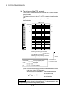
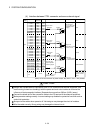
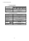
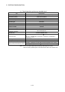
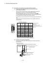
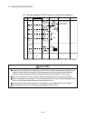
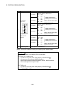
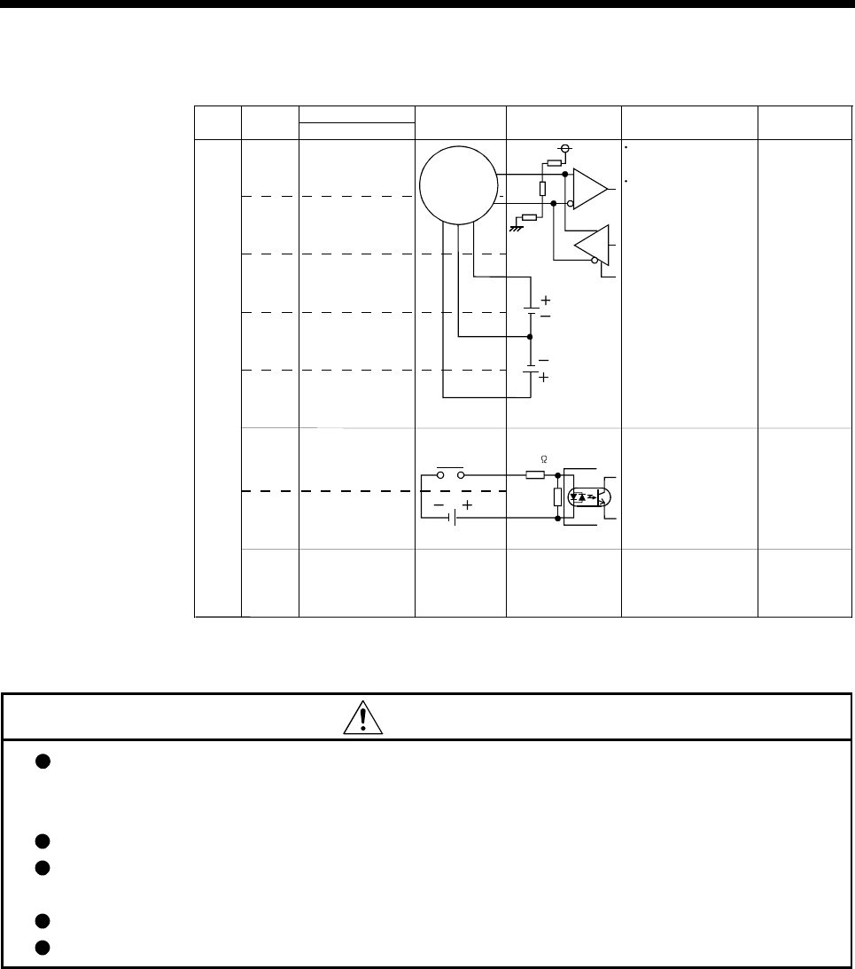
(5) Interface between SY.ENC connector and external equipment
Pin No.
SY.ENC connector
Serial
absolute
synchronous
encoder
Input or
Output
Signal
name
Wiring example
12VDC to 24VDC
Input
MR 7
MRR 17
P5 10 18 19 20
LG 1 2 3 11 12
BAT 9
TREN 4
TREN.
COM
14
SD
5VDC
Battery
plate
Internal circuit Specification Description
Transmission method:
serial communications
Position detection
method: absolute
5.6K
(Note)
(Note)
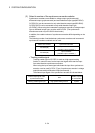
(Note) : As for the connection to power line (TREN, TREN.COM), both "+" and "–" are possible.
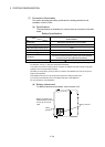
CAUTION
Always use a shield cable for connection of the SY.ENC connector and external equipment, and
avoid running it close to or bundling it with the power and main circuit cables to minimize the
influence of electromagnetic interface. (Separate them more than 200mm (0.66 ft.) away.)
Connect the shield wire of the connection cable to the FG terminal of the external equipment.
When increasing the cable length, use the cable 30m(98.43ft.) or less. Note that the cable should
be run in the shortest possible distance to avoid induced noise.
Always wire the cables when power is off. Not doing so may damage the circuit of modules.
Wire the cable correctly. Wrong wiring may damage the internal circuit.