


6 - 27
6 INSPECTION AND MAINTENANCE
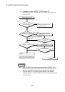
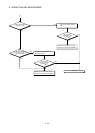
(2) Output circuit troubleshooting and corrective action
This section describes troubleshooting with output circuits and their corrective
actions.
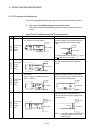
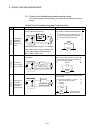
Output Circuit Troubleshooting and Corrective Action
Condition Cause Corrective action
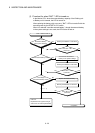
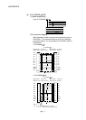
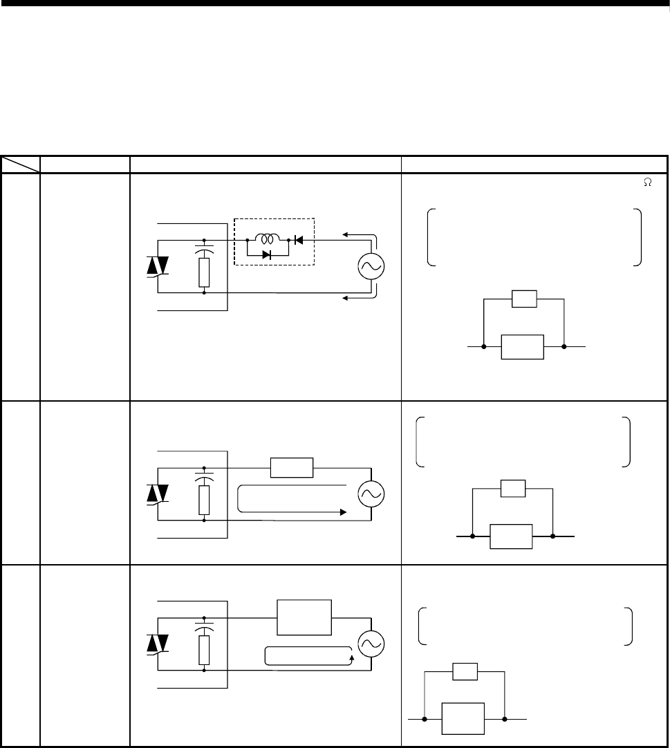
Example 1
Overvoltage
applied to
load when
output turns
OFF
• If load is internally half-wave rectified
(some solenoids are like this).
Output module
D1
Load
1)
2)
• With polarity of power supply 1), C is charged.
With polarity 2),the C charge voltage plus the
power supply voltage is applied across D1.
Max. voltage is approx. 2.2E.
• Connect a resistor between several tens k
and several hundreds k across the load.
Load
Resistor
This method causes no problems with
output terminals but lead to deterioration
or burnout of load internal diodes.
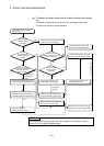
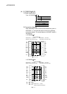
Example 2
Load does
not turn OFF
(Triac output).
• Leakage current due to built-in surge
suppressor.
Output module
Load
Leakage current
• Connect a resistor across the load.
Load
Resistor
If long wiring exists between the output
card and the load, leakage currents also
arise due to wiring capacity.
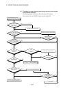
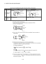
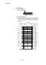
Example 3
Time period
fluctuates
when load is
a CR timer
(Triac output)
Output module
CR timer
Leakage current
• Drive a relay and use the contacts to drive
the CR timer.
CR
timer
Resistor
Calculate resistor
constant from load.
Be careful of example 1, as some
timers are half-wave rectified
internally.