


78
Epsilon EP-I Indexing Drive and FM-2 Indexing Module Reference Manual
RMS Foldback
RMS foldback protects the motor from overheating. The RMS Foldback parameter models the thermal heating and cooling
of the drive and motor based on the commanded current and the motor velocity. On power-up, the RMS Foldback level is
zero and is continually updated. When the RMS Foldback level reaches 100 percent, current foldback is activated and the
Foldback Active output function is active.
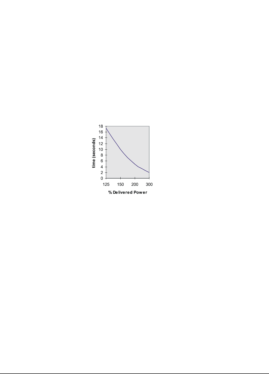
Each drive is designed to deliver up to 300 percent of the motor’s continuous torque for no less the two seconds when running
at 100 RPM or more. If only 150 percent of continuous torque is required, several seconds of operation before RMS foldback
is typical.
During current foldback the Torque Command Actual will be limited to 80 percent continuous motor torque. Current foldback
is cancelled when the RMS Foldback level falls below 70 percent. This could take several seconds or several minutes
depending on the load.
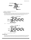
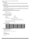
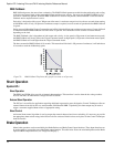
The RMS Foldback value is dependent on both torque and velocity. At low speeds (<20 percent of maximum motor speed)
the RMS Foldback will closely follow the Torque Command Actual. At high speeds (>50 percent of maximum motor speed)
the RMS Foldback will read higher than the Torque Command Actual.
The time constant for RMS Foldback is 10 seconds. This means that if the load is 150 percent of continuous, it will take about
10 seconds to reach the foldback trip point.
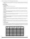
Figure 79: RMS Foldback Trip Point (this graph is accurate to ±5 percent)
Shunt Operation
Epsilon EP-I
Shunt Operation
The EP204 and EP206 drives provide an internal shunt transistor. This transistor is active when the bus voltage reaches
405Vdc and shuts off when the bus voltage falls below 390Vdc.
External Shunt Operation
The DC bus is accessible for applications requiring additional regenerative power dissipation. Control Techniques offers an
external shunt resistor kit for this use, model number: SM-Heatsink DBR-1. Optionally, the shunt output may be used to
trigger a customer supplied shunt resistor of appropriate rating.
Shunt Control
An internal shunt control algorithm is used to prevent the external shunt resistor from overloading. It is necessary to provide
the appropriate shunt resistor ratings in the PowerTools Pro software. Default values are in place for the Control Techniques
shunt resistor kit.
Brake Operation
Motor brake operation can be controlled by the Brake Release and Brake Control input functions. These input functions can
be used together to control the state of the Brake output function. The table below shows the relationship between the Brake
input and Brake output functions (see “Diagnostic Display”).