


74
Epsilon EP-I Indexing Drive and FM-2 Indexing Module Reference Manual
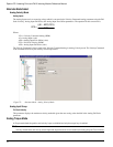
Differential Source
The Differential setting (default) is perfect for most encoders or upstream drives. The differential input circuit is RS-422
compatible making it inherently noise immune while being able to accept pulse rates of up to 1.75 Mhz per channel.
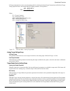
Single Ended Source
The Single Ended setting is a good match for any open collector driver that requires an external pull up resistor making it
ideal for most stepper controllers, PLC stepper cards and PC computer parallel printer ports. The single ended inputs use high
noise immunity circuitry and have internal pull-up resistors to the drive’s 5 Volt logic supply so external pull-ups and biasing
circuitry is not required.
The two hardware input circuits are included in the drive and are accessible through the drive command connector. When
proper installation techniques are followed as shown below, the differential input setup will provide a more robust and noise
immune system than a single ended input setup.
Differential input is recommended under any of the following conditions:
• Pulse width < 2 µs
• Pulse frequency > 250 kHz
• Pulse command cable length > 25 feet
• Noisy electrical environments
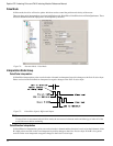
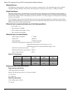
Differential input circuit specifications:
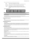
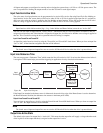
Epsilon EP-I Wiring Example:
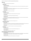
Single ended input circuit specifications:
Single ended input specifications:
1 MHz input frequency maximum
Internal 330 ohm pull-up resistors to 5 Volt (non-isolated)
1.5 V low level
3.5 V high level
Output driver requirements:
15 mA sinking (open collector)
5 V capacity
Input frequency maximum: 1.75 Mhz
Input device: AM26C32
Input impedance: 12 Kohms each input
Maximum voltage applied to input pins (A, A/) or (B, B/):
Single Ended (referenced to 0V drive logic):+/-10 V
Differential (referenced to mating differential input):+/-10 V
Maximum common mode voltage: +/-7 V
Minimum differential voltage required: 200 mV
Input voltage hysteresis: 60 mV
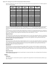
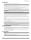
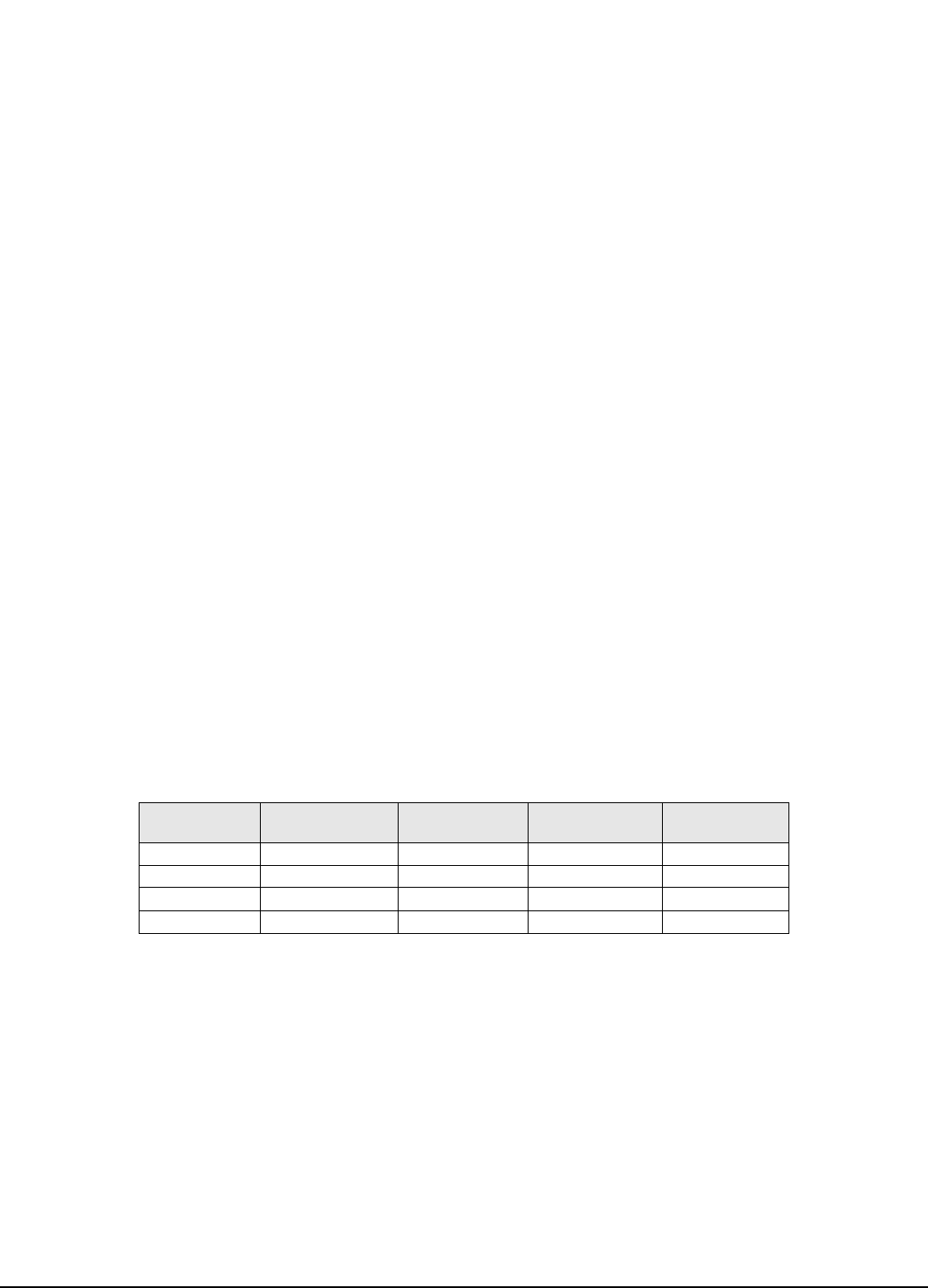
STI-SNCI Terminal Sync Connector Pin #
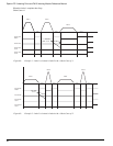
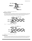
Pulse-Direction
Signal
Pulse-Pulse
Signal
Pulse Quadrature
Signal
Sync Enc In “A” 1 Pulse Pulse + A
Sync Enc In “A/” 2 Pulse/ Pulse +/ A/
Sync Enc In “B” 3 Direction Pulse - B
Sync Enc In “B/” 5 Direction/ Pulse -/ B/