124
Epsilon EP-I Indexing Drive and FM-2 Indexing Module Reference Manual
Encoder signals are used for commutation. Incorrectly wired encoder signals can cause damage to the drive.
Step 3:Determine Encoder Alignment
In order for the drive to commutate with a motor correctly, it must know how the encoder commutation tracks and how the
marker pulses are aligned with respect to the R, S and T windings in the stator. The drive does not require any particular
alignment position but instead allows the alignment to be specified using the Motor Encoder U Angle and Motor Encoder
Marker Angle parameters.
If the motor under test has a defined encoder alignment which is repeated on all similar motors, simply determine the proper
angles then use the same settings on all similar motors.
If the motor under test does not have a specific encoder alignment, you should establish some standard mechanical alignment
before determining and setting the encoder electrical angles. This will allow you to replace the motor with another one in the
same alignment without going through this procedure each time.
Reading Encoder Alignment
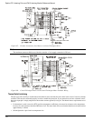
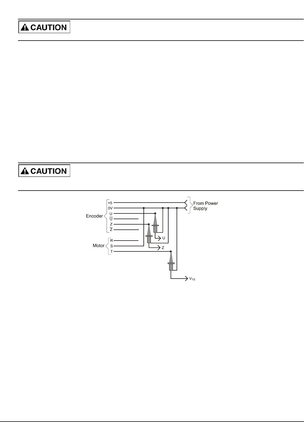
The reference motion for this test can be either CW or CCW. We will first use CCW. An oscilloscope will be used to monitor
the signals. This procedure must be performed with the motor disconnected from the drive with the exception of the encoder
power supply.
Be careful when using the drive encoder power supply for testing a motor. Shorting the 5V drives encoder power supply
will blow an internal fuse which can only be replaced at the factory.
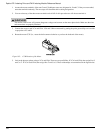
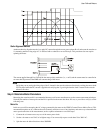
Figure 111: Oscilloscope Connections
CCW Reference Rotation
Before reading the motor signals, zero the V
TS
oscilloscope channel on a horizontal graduation marker to allow more accurate
readings.
Couple the drill motor to the motor shaft. While spinning the motor counter-clockwise, use an oscilloscope to examine the
phase relationship between encoder channel U and positive peak of V
TS
(the voltage at motor power terminal T with reference
to S).
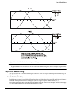
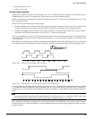
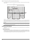
Use the figure below to determine the electrical angle at which the rising edge of U occurs. This is the Motor Encoder U
Angle. Note that with a CCW reference rotation the positive peak of V
TS
is at zero electrical degrees and the electrical angle
decreases from left to right.


