


142
Epsilon EP-I Indexing Drive and FM-2 Indexing Module Reference Manual
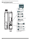
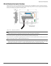
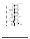
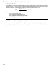
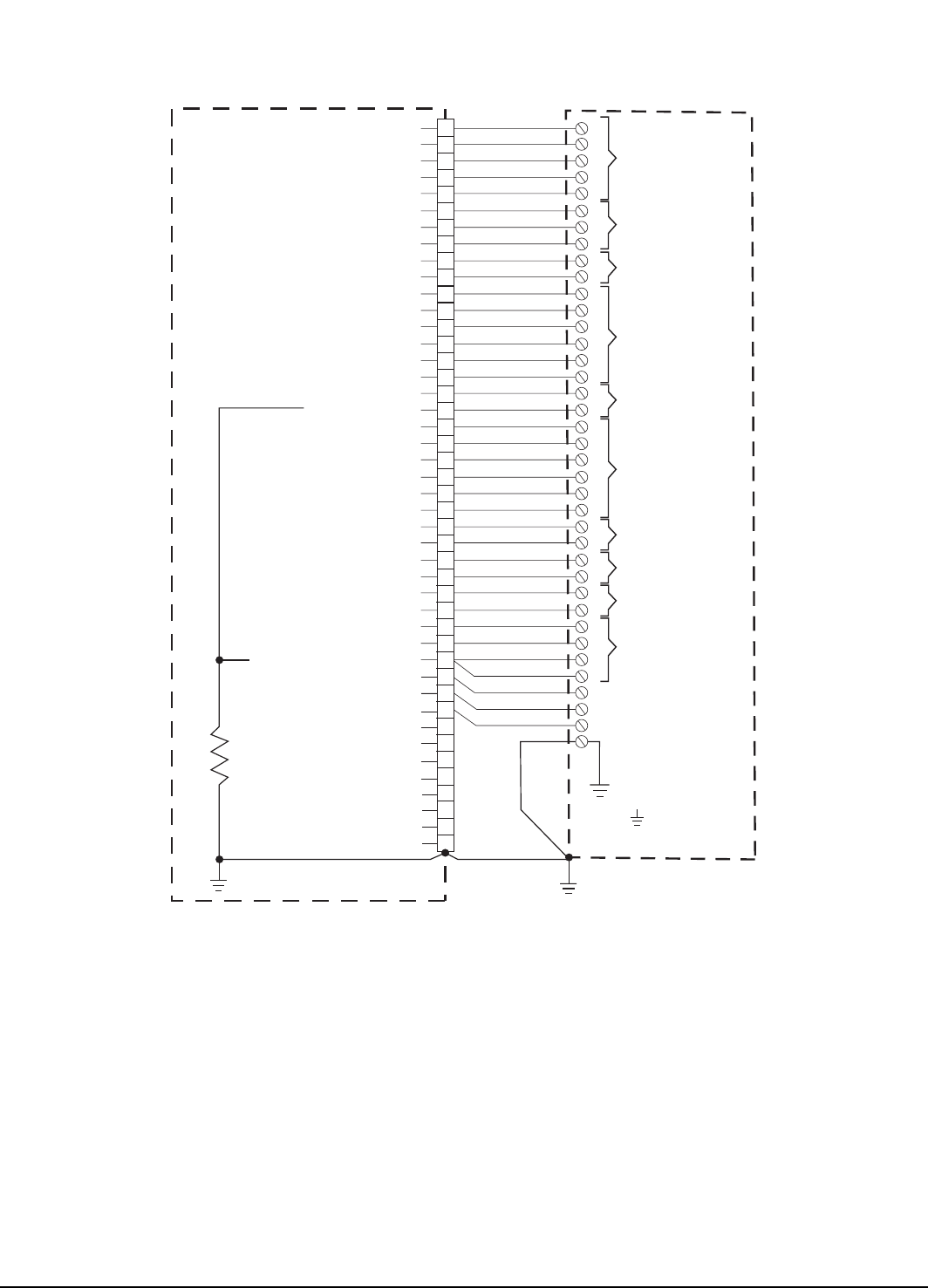
Figure 119: ECI-44 Signal Connections
AG
+2
+1
Analog Out
AG
Command Input
+
-
-
-
I/O P.S. 0 V
+
+
I/O P.S. 24 V
EN V+
NC2
NC1
NC = No Connection
DG = Digital Ground
AG = Analog Ground
= Shield Ground
Inputs
1
2
3
4
EN
3
1
2
Outputs
-
+
RS-485
A/
A
B/
B
Z/
Z
Motor Encoder Output
A/
A
B/
B
Z/
Z
Sync Encoder Output
DG
+5
Ext Encoder Supply
Output (200 mA max)
Screw Terminals on ECI-44
Command Connector
on Drive (J5)
(Connector shell and
strain relief points)
Input #3
Input #4
Drive Enable Input
Output #3
Output #2
Output #1
RS 485 +
RS 485 -
Encoder Output Channel A
Encoder Output Channel A/
Encoder Output Channel B
Encoder Output Channel B/
Encoder Output Channel Z
Encoder Output Channel Z/
Encoder Supply +5 Volts
Encoder Common
Pulse Input A
Pulse Input B/
Pulse Input B
Pulse Input Z
Pulse Input Z/
- Analog Command In
Diagnostics Output Channel 1
Diagnostics Output Channel 2
Diagnostics Output Common
+ Analog Command In
I/O Supply +
I/O Supply +
I/O Common -
I/O Common -
Pilse Input A, Single Ended
Pulse Input B, Single Ended
Do Not Connect
Do Not Connect
Do Not Connect
Do Not Connect
Do Not Connect
Do Not Connect
Do Not Connect
Do Not Connect
10 Ohm
PE Ground
Connector Shell
+ 15 V, 10 mA
Pulse Input A/
Input #2
Input #1
1
2
3
4
16
17
18
19
9
23
24
37
38
11
12
27
41
40
26
25
39
34
33
32
31
15
14
43
44
29
28
20
36
5
7
10
13
35
22
30
42
6
21
8