123
User Defined Motors
• Voltage rating min: 10 Vdc
• I capacity min: 1 mA
Encoder Logical Interfacing
The encoder is expected to provide six logical signals: A, B, Z, U, V and W. Each of these signals is received at the drive by
a differential receiver circuit. For example, the A logical signal is received as channels A and /A.
Signals A and B provide incremental motor position in quadrature format. Z is a once per revolution marker pulse. U, V and
W are commutation tracks.
There are two steps in interfacing the encoder signals:
1. Determine whether your encoder has all the required signals to operate with a drive. Some encoders, for example, do not
provide a marker pulse or the marker pulse may not have a fixed phase relationship to the commutation tracks.
2. Determine the mapping from the motor encoder signals to the drive. To help with this second step we have provided a
description of the required characteristics of the A, B, Z, U, V and W encoder signals.
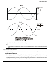
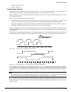
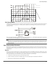
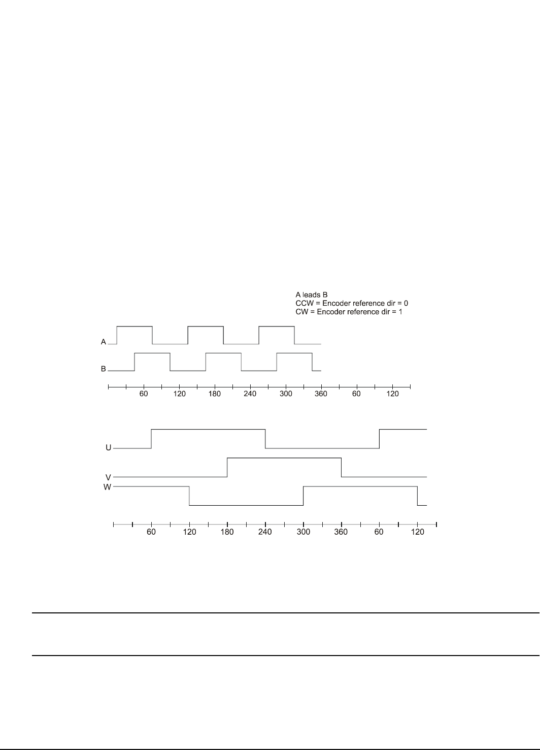
The signal relationships of A, B, U, V and W required by the drive are shown in the phase plots below. For clarity the time
scale against which A and B are plotted is different from that which U, V and W are plotted. Note that A leads B and U leads
V and V leads W.
Plots like these are obtained by powering the encoder then rotating the motor while observing the signals on an oscilloscope.
It is important to note which direction of motor rotation (CW or CCW) generates the phasing shown in the figures below.
Figure 109: Phase Plot of A and B Encoder Channels
Figure 110: Phase Plot of U, V and W Encoder Signals with CCW Rotation
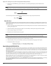
If the signal phasing in the figure above is obtained by rotating the motor -, the Motor Encoder Reference Motion is defined
as - and the Motor Encoder Reference Motion parameter is set to 0. If the signal phasing in the figure above is obtained by
rotating the motor +, then the Motor Encoder Reference Motion is defined as + and the Motor Encoder Reference Motion is
set to 1.
Note
It is important that all the encoder phases match the phase plot in the figure above. (i.e., A leads B, U leads V and V leads
W. No particular phase relationship is required between the A and B pair and the U, V, W signals.
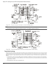
Drive signal names are relatively standard. Your encoder signals may be named differently or they may have the same names
but the signals may be functionally different. You must determine the proper encoder signal mapping to correctly wire your
encoder to a drive.


