


73
Operational Overview
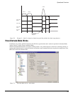
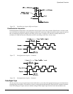
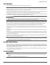
Figure 76: Pulse/Direction Signals, Differential Inputs
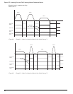
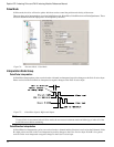
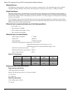
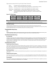
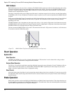
Pulse/Quadrature Interpretation
In Pulse/Quadrature interpretation, a full quadrature encoder signal is used as the command. When B leads A encoder counts
are received they are interpreted as positive changes to the Pulse Position Input. When A leads B encoder counts are received
they are interpreted as negative changes to the Pulse Position Input. All edges of A and B are counted, therefore one
revolution of a 2048 line encoder will produce an 8192 count change on the Pulse Position Input.
Figure 77: Pulse/Quadrature Signals, + Command
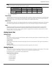
Figure 78: Pulse/Quadrature Signals, – Command
Pulse Signal Type
The drive provides two types of pulse input circuits which allows you to choose the appropriate input type to match the device
generating the position pulses. The selection is done by wiring to the desired input pins of the base drive command connector
or the EP-I analog/sync output connector and then setting the Pulse Signal Type selection in the Alternate Mode view.